Modeling of Communication Requirements in Five Typical Application Scenarios
In the actual engineering deployment of a Battery Management System (BMS), the selection of communication protocols is not an isolated technical decision, but a systematic design process deeply coupled with specific application environments, system architectures, reliability requirements, and cost boundaries. Different application scenarios propose significantly different requirements for communication mechanisms—from high-real-time multi-node coordination in electric vehicles to signal integrity challenges brought by long-distance wiring in energy storage systems; from the design constraints of extremely limited pin resources in consumer electronics, to the stringent guarantees for data integrity under extreme environments in the aerospace field. These scenarios not only determine the adaptability of physical layer protocols but also affect the topology structure, fault tolerance mechanisms, and scheduling strategies of the entire communication link.
This chapter will conduct an in-depth analysis of five representative BMS application scenarios to construct a communication requirement model based on actual working conditions. By introducing a quantifiable index system (such as latency tolerance, bit error rate threshold, node expansion capability, EMC level, etc.), combined with typical system architecture diagrams and protocol behavior flowcharts, it reveals the essential contradictions and optimization paths of communication design in different scenarios. Each application will start from its core challenges to derive specific requirements for Key Performance Parameters (KPPs) of communication protocols, supplemented by parameter configuration cases and code implementation snippets in real systems, ensuring a high degree of unity between theoretical modeling and engineering practice.
Electric Vehicle Battery Management System (EV-BMS)
As one of the core subsystems of modern new energy vehicles, the power battery management system undertakes multiple key tasks such as voltage, current, and temperature acquisition, SOC estimation, equalization control, thermal management linkage, and fault warning. Its communication architecture must support efficient coordination among tens to hundreds of battery cell modules while meeting the data interaction needs of the Vehicle Control Unit (VCU), Motor Control Unit (MCU), and On-Board Diagnostics (OBD) system. In this complex context, the reliability, real-time performance, and scalability of the communication system become the key factors determining the safety and performance of the entire vehicle.
Communication Challenges of Multiple Slave Nodes and High Reliability
In a typical EV BMS architecture, a distributed structure of “Main Control Unit + Multiple Slave Acquisition Modules” (Main BMS + Slave BMUs) is usually adopted. Each Slave BMU is responsible for sampling the voltage and temperature of a group of series-connected battery cells and reports the data to the Main BMS through the communication bus. Taking a battery pack composed of 100 battery cells on an 800V high-voltage platform as an example, it often needs to be divided into 10 to 20 acquisition modules, forming a multi-node, high-concurrency communication network.
The core problem facing this architecture is: how to ensure the timely upload of data from all slave nodes under limited bandwidth while avoiding information loss caused by bus congestion or arbitration failure? Especially when a fault occurs (such as single-cell overvoltage or abnormal temperature), the relevant modules must be able to preempt communication resources with priority, ensuring that the main control unit can receive the warning information within milliseconds.
To address this challenge, the CAN bus is widely adopted due to its natural non-destructive bit arbitration mechanism. Its message identifier (CAN ID) is not only used for addressing but also implies a priority attribute—the smaller the ID value, the higher the priority. Therefore, the following ID allocation strategy is often designed in an EV-BMS:
| Message Type | CAN ID (Standard Frame, 11-bit) | Usage Description |
| Fault Alarm | 0x101 | Shared by all BMUs, sent immediately after triggering |
| Real-time Status | 0x201 ~ 0x214 | Independent ID for each BMU, reported periodically |
| Equalization Command | 0x301 | Issued by the main controller, controls specific modules to start equalization |
| SOC Synchronization | 0x401 | Main controller broadcasts the current estimation result |
// Example of CAN message transmission function in EV-BMS (based on STM32 HAL library)void CAN_SendMessage(uint32_t can_id, uint8_t *data, uint8_t len) {CAN_TxHeaderTypeDef txHeader;uint32_t txMailbox;txHeader.StdId = can_id; // Set standard IDtxHeader.RTR = CAN_RTR_DATA; // Data frametxHeader.IDE = CAN_ID_STD; // Standard frame modetxHeader.DLC = len; // Data lengthtxHeader.TransmitGlobalTime = DISABLE;if (HAL_CAN_AddTxMessage(&hcan1, &txHeader, data, &txMailbox) != HAL_OK) {Error_Handler(); // Handle transmission failure}
}
Code logic analysis:
- txHeader.StdId = can_id;: Sets the standard identifier of the CAN message, which directly affects the arbitration priority.
- The RTR and IDE fields respectively define the frame type (remote request/data frame) and identifier format (standard/extended).
- DLC must strictly match the actual data length; anything exceeding 8 bytes will be truncated.
- HAL_CAN_AddTxMessage() is a non-blocking call; a successful return simply indicates the message has entered the transmission queue, but does not guarantee successful delivery.
It is worth noting that although CAN has good multi-node support capabilities, when the number of nodes exceeds 15 and the sampling frequency reaches a 10ms cycle, the bus load may approach over 70%, posing a risk of latency fluctuations. To this end, advanced BMS systems often introduce the CAN FD (Flexible Data-rate) protocol, which allows the use of classic CAN rates (such as 500kbps) in the arbitration phase, and switches to a higher baud rate (such as 2Mbps) in the data phase, thereby increasing the effective throughput.
Furthermore, to enhance reliability, many manufacturers implement a “dual-channel redundant CAN” architecture at the software layer, where the Main BMS is equipped with two sets of independent CAN controllers connected to different physical lines, forming a hot standby mechanism. When the main channel detects transmission timeouts three consecutive times, it automatically switches to the backup channel and triggers a fault record.
The main controller continuously monitors the transmission and reception status of both channels, and once it finds consecutive errors on the main channel (such as missing ACKs or CRC validation failures), it initiates the switching logic. This design significantly improves the system’s survivability under harsh conditions like vibrations and electromagnetic interference.
However, redundancy also brings new problems: how to ensure data consistency across the two channels? A common solution is to set a “timestamp comparison window” at the receiving end, accepting only the first valid message to arrive and ignoring subsequent duplicate frames. This requires all nodes to have an accurate time synchronization mechanism, typically achieved by periodically broadcasting a time reference message.
In summary, multi-node communication in EV-BMS is not only a matter of protocol selection but also a comprehensive system engineering problem involving ID planning, traffic scheduling, error recovery, and redundant switching. Only on the basis of fully understanding the interaction logic at all levels can a truly high-reliability communication framework be constructed.
Real-time Status Reporting and Fault Response Requirements
During the operation of an electric vehicle, changes in battery status are highly dynamic, especially under working conditions such as rapid acceleration, regenerative braking, or high-temperature fast charging, where cell voltage and temperature may experience severe fluctuations. Therefore, the BMS must be able to complete data acquisition, transmission, processing, and response within an extremely short time; otherwise, it may lead to delayed protective actions and cause safety hazards.
According to the ISO 26262 functional safety standard, the BMS belongs to an ASIL-D level system, requiring the end-to-end latency of critical signals not to exceed 100ms. For certain specific events (such as insulation faults or short-circuit prediction), a closed-loop response is even required to be completed within 20ms. This means that from the moment a Slave BMU detects an anomaly to the moment the Main BMS makes the decision to cut off the relay, the entire communication link must possess deterministic latency characteristics.
To achieve this, EV-BMS generally adopts a hierarchical scheduling mechanism:
- Periodic tasks: Report basic parameters such as voltage, temperature, and current once every 10ms;
- Event-driven tasks: Once an out-of-limit condition is detected (e.g., cell voltage > 4.3V), immediately interrupt the current cycle, preempt the bus, and send a fault message;
- Low-frequency tasks: Update slow-changing parameters such as SOC and SOH once every 1s. Below is a typical code snippet for interrupt-triggered fault reporting;
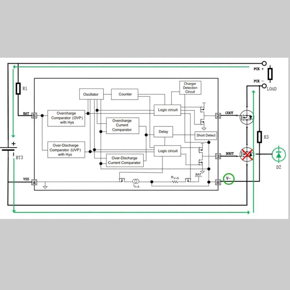
// Monitor cell voltage limit in Slave BMU and trigger CAN interruptvoid Voltage_Monitor_ISR(void) {float cell_voltage = ADC_Read_CellVoltage();if (cell_voltage > OVER_VOLTAGE_THRESHOLD) {uint8_t fault_data[4] = {0};fault_data[0] = CELL_ID;fault_data[1] = (uint8_t)(cell_voltage * 100); // Encoded as 0.01V precisionfault_data[2] = get_temperature();fault_data[3] = 0x01; // Flag bit: OvervoltageCAN_SendMessage(0x101, fault_data, 4); // High priority IDSet_Fault_Flag(); // Set local fault flag}}
Parameter Description and Logic Analysis:
- OVER_VOLTAGE_THRESHOLD: Generally set to 4.25V~4.30V, leaving a certain margin to prevent false triggers; A
- DC_Read_CellVoltage(): Precision measurement via Σ-Δ ADC, with resolution up to 1mV;
- CAN_SendMessage(0x101, …): Uses the highest priority ID, ensuring it can be sent in the very next CAN frame gap;
- Set_Fault_Flag(): Notifies the local state machine to enter fault mode, stop equalization operations, and wait for main control commands.
It is worth noting that even with a high-priority ID, bus contention caused by multiple nodes reporting faults simultaneously cannot be completely ruled out. Although the CAN protocol supports non-destructive arbitration, if multiple nodes send messages with the same ID (such as a shared fault ID), their sources cannot be distinguished, causing a “source unknown” problem.
One solution to this problem is to introduce a time-sliced retransmission mechanism: when a node attempts to send a fault message but fails (detects bus busy or no ACK), it waits for a random backoff time before retrying. The backoff time can be generated based on a node address hash to avoid multiple nodes retrying synchronously. Another more advanced approach is to use CAN FD with ISO TP (ISO 15765-2) to encapsulate long messages, carrying complete context information (including timestamps, sequence numbers, source addresses, etc.), making it easier for the main controller to perform deduplication and sorting. In addition, to verify whether real-time performance meets standards, engineers need to establish an end-to-end latency test model:
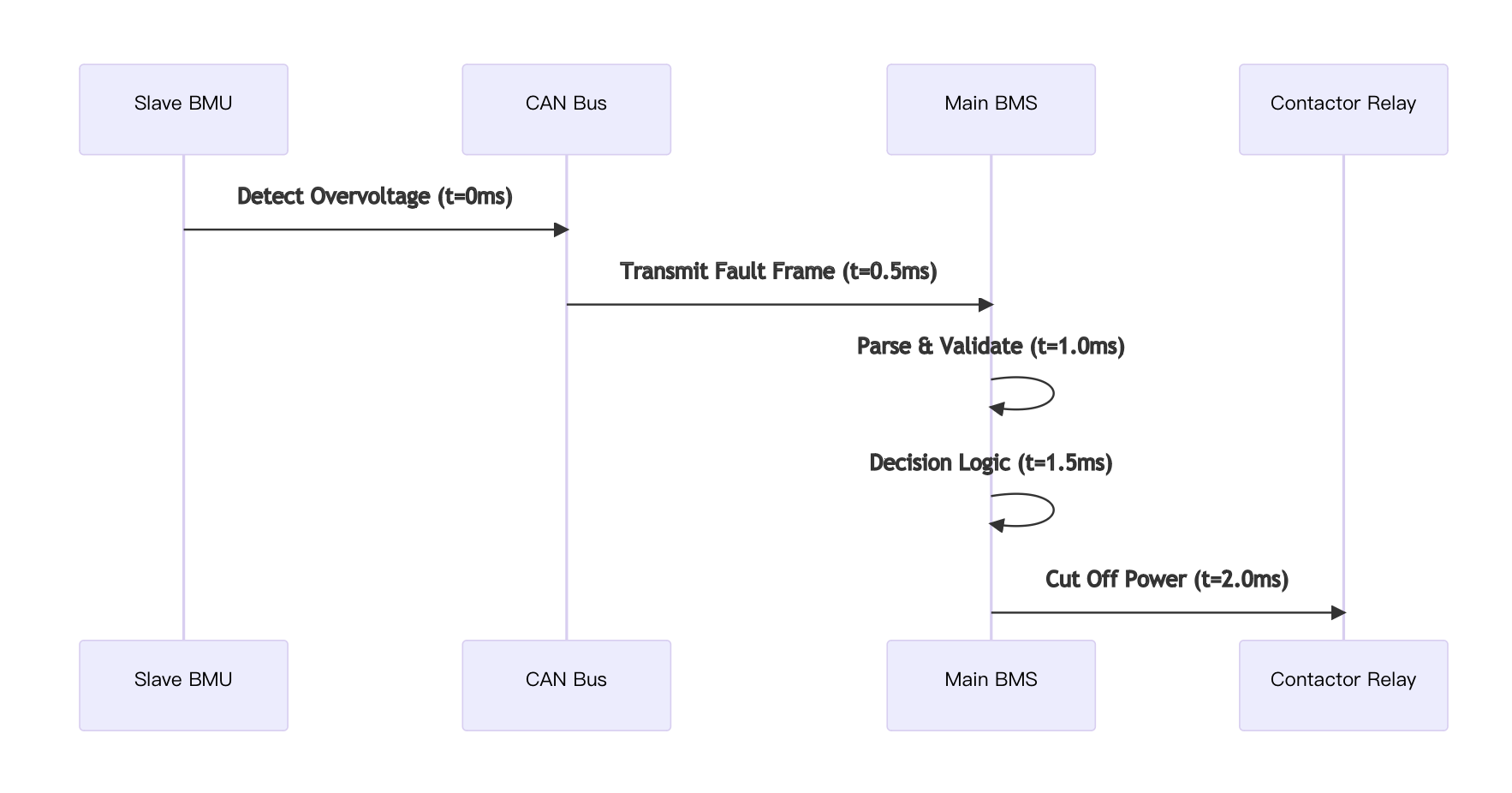
The timing diagram shows that under ideal conditions, the entire response link can be completed within 2ms. But in actual vehicles, factors such as PCB trace latency and contactor mechanical action time (about 10~30ms) must also be considered. Therefore, the communication portion must be compressed to within 5ms as much as possible, leaving a sufficient time window for actuators.
In conclusion, the communication design of an EV-BMS should focus not only on “whether communication is possible” but also on “when to communicate” and “in what order to communicate.” Only by integrating real-time performance, determinism, and fault tolerance can the requirements of high-level functional safety be met.
Module-Level Communication in Energy Storage Systems (ESS)
With the continuous increase in renewable energy penetration, large-scale Energy Storage Systems (ESS) have become important supports for grid peak shaving, frequency regulation, and emergency power supply. Unlike the compact layout of electric vehicles, an ESS is often composed of hundreds to thousands of battery modules, distributed across multiple cabinets or even deployed across plants, with communication distances reaching over 100 meters. This long-distance, high-capacity, and distributed system structure poses brand new challenges for BMS communication.
Long-Distance Wiring and Anti-Interference Requirements
In a typical containerized energy storage system, each battery cluster contains several battery cabinets, and each cabinet integrates multiple Battery Management Units (BMUs). The central control unit (Central BMS) is usually located in the central control room and needs to maintain connections with remote modules via communication buses. Due to wide geographical distribution, communication lines are extremely susceptible to Electromagnetic Interference (EMI) such as power frequency interference, switching power supply noise, and lightning induction.
Traditional I2C or SPI protocols are limited by their electrical characteristics, with a maximum recommended transmission distance of only a few meters, clearly inadequate for such scenarios. However, relying on differential signal transmission (CAN_H/CAN_L), terminal resistor matching, and CRC validation mechanisms, the CAN bus can theoretically support a communication distance of up to 1km (at a 50kbps rate). Therefore, CAN has become the most mainstream communication choice in ESS.
However, even when using CAN, the physical layer must still be carefully designed to cope with long-line effects. The main issues include: Signal reflection: An incorrectly terminated bus will generate echoes at the ends, superimposing on the original signal and causing distortion; Attenuation and distortion: Cable impedance increases with length, causing a drop in signal amplitude; Common-mode interference: Ground potential differences cause reference voltage drift, affecting the receiver’s decision threshold. To address this, the following design specifications must be followed:
| Parameter | Recommended Value | Description |
| Baud Rate | ≤ 125 kbps | The longer the distance, the lower the rate should be |
| Terminal Resistor | 120Ω ±1% | Add one at each end, no addition for intermediate nodes |
| Cable Type | Shielded Twisted Pair (STP) | Characteristic impedance around 120Ω |
| Grounding Method | Single-point grounding | Prevents ground loops |
| Driving Capacity | Support at least 32 nodes | Consider future expansion |
In addition, to improve noise immunity, it is recommended to add a magnetic bead + TVS diode combination filter circuit at the entrance of each BMU, and use an isolated CAN transceiver (such as TI’s ISO1050 or NXP’s MC33662) to achieve electrical isolation between power and signals.
// Initialize isolated CAN interface (taking STM32 + ISO1050 as an example)void CAN_Isolated_Init(void) {GPIO_InitTypeDef gpio;// Configure CAN_RX / CAN_TX pinsgpio.Pin = GPIO_PIN_11 | GPIO_PIN_12;gpio.Mode = GPIO_MODE_AF_PP;gpio.Alternate = GPIO_AF9_CAN1;gpio.Pull = GPIO_PULLUP;HAL_GPIO_Init(GPIOA, &gpio);// Enable CAN clock and interrupts__HAL_RCC_CAN1_CLK_ENABLE();HAL_NVIC_SetPriority(CAN1_RX0_IRQn, 0, 0);HAL_NVIC_EnableIRQ(CAN1_RX0_IRQn);// Configure CAN working modehcan1.Instance = CAN1;hcan1.Init.Prescaler = 16; // Prescalerhcan1.Init.Mode = CAN_MODE_NORMAL;hcan1.Init.SyncJumpWidth = CAN_SJW_1TQ;hcan1.Init.TimeSeg1 = CAN_BS1_12TQ; // Propagation segment + Phase buffer segment 1hcan1.Init.TimeSeg2 = CAN_BS2_8TQ; // Phase buffer segment 2hcan1.Init.AutoBusOff = ENABLE;hcan1.Init.AutoWakeUp = DISABLE;hcan1.Init.AutoRetransmission = ENABLE; // Automatic retransmissionhcan1.Init.ReceiveFifoLocked = DISABLE;hcan1.Init.TransmitFifoPriority = DISABLE;if (HAL_CAN_Init(&hcan1) != HAL_OK) {Error_Handler();}}
Line-by-line parsing:
- Prescaler = 16: Combined with the APB1 clock (assumed to be 48MHz), the calculated time quantum TQ = 16/(48M) = 333ns;
- TimeSeg1 = 12TQ, TimeSeg2 = 8TQ: The total bit time is 21TQ, corresponding to a baud rate ≈ 48MHz / (16×21) ≈ 142.8kbps;
- AutoRetransmission = ENABLE: Enables automatic retransmission, increasing the success rate in weak signal environments;
- AutoBusOff: When a node consecutively transmits errors up to 128 times, it automatically disconnects from the bus to prevent dragging down overall performance.
Despite adequate protections at the hardware level, occasional packet loss may still occur in long-distance communication. For this reason, an acknowledgment mechanism should be introduced at the application layer. For example, after the main controller sends a query command, if no response is received within a specified time, it marks the node as offline and attempts to reinitialize it.
Module Hot-Swapping and Dynamic Network Topology Adjustment
In large-scale ESS systems, O&M personnel often need to replace or upgrade individual faulty modules, which requires the communication system to support a “hot-swap” function—that is, plugging in or removing a certain BMU without shutting down the system and without affecting the normal operation of other nodes.
However, the standard CAN protocol itself does not directly support dynamic node management. When a new module is powered on, if it immediately participates in communication, it may disrupt the existing network due to ID conflicts or synchronization failures. Therefore, a complete hot-swap recognition and registration mechanism must be designed. A common solution is as follows:
- The main controller periodically broadcasts a “heartbeat query” message (ID=0x100);
- The newly joined BMU listens to this message, and upon receiving it, delays for a short period (e.g., 50ms) before replying with a “registration request”;
- After verifying the legitimacy of its ID, the main controller assigns a unique address and allows it to join the regular communication loop;
- If a node fails to respond to heartbeats 3 consecutive times, it is deemed offline, and its resources are released.
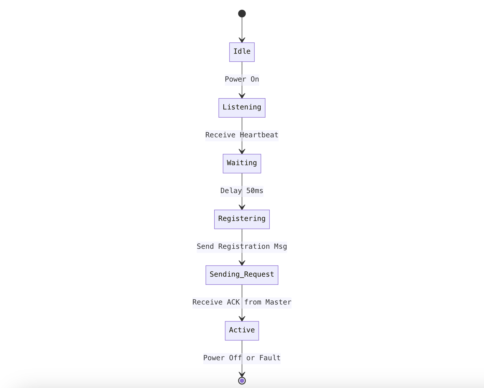
This state machine clearly describes the behavior transition logic of hot-swapped nodes. By introducing a delay mechanism, conflicts caused by multiple new nodes rushing to answer simultaneously are avoided.
In addition, to support flexible topologies, some high-end ESS systems use the CANopen protocol stack, utilizing its built-in Node Guarding or Heartbeat mechanisms to achieve online monitoring. CANopen also defines a standardized Object Dictionary, allowing interoperability among modules from different manufacturers, which greatly enhances system openness and maintainability.
In conclusion, the communication design of energy storage systems must balance the two major goals of “distance” and “stability.” Only through reasonable physical layer selection, isolation measures, and protocol enhancement mechanisms can enduring and reliable inter-module collaboration be achieved in complex industrial environments.