During an intensive care transport scenario, a patient on a mechanical ventilator relies on a smart lithium-ion battery pack as the main utility power source seamlessly disengages. Suddenly, a transient voltage spike from an auxiliary defribrillator fires through the system power rail, causing the primary Battery Management System (BMS) field-effect transistor (FET) driver to latch in a closed state. In standard consumer electronics, an unmitigated secondary overcharge or overvoltage condition could lead to thermal runaway. In life-critical care instruments, single-point electrical failures are completely unacceptable. Implementing a dual protection BMS architecture ensures that if primary software or analog front-end (AFE) controls fail, an independent secondary hardware circuit triggers permanent electrical isolation. This multi-layered redundancy preserves equipment operational integrity, protects patients and clinical staff, and satisfies global medical device safety regulations.
Primary Software-Monitored Protection vs. Secondary Hardware Redundancy
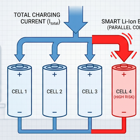
In critical care battery design, relying on a single protection IC exposes the host device to single-point failure modes. A dual protection BMS architecture splits safety responsibilities between a primary intelligent management system and a secondary, hardware-enforced fail-safe layer.
Primary BMS Control and Smart Telemetry
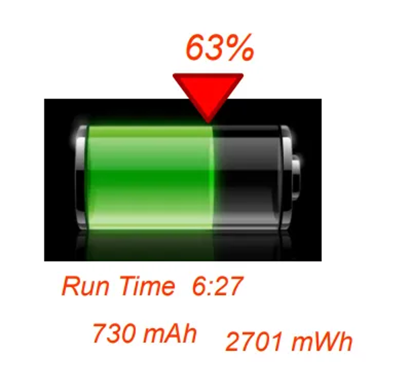
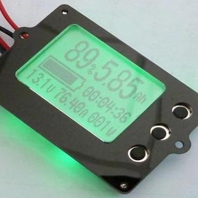
The primary protection layer consists of an advanced AFE and fuel gauge IC operating via SMBus v1.1 protocol communication. This system continuously monitors individual cell voltages, pack current, and temperature, dynamically managing charge and discharge MOSFETs. It enforces software-level trip thresholds, reporting real-time State-of-Charge (SOC), State-of-Health (SOH), and status flags directly to the critical care instrument’s host processor.
Secondary Independent Hardware Cutoff Circuitry
Operating completely isolated from the primary BMS microcontroller, the secondary protection IC monitors cell string voltages independently. It does not communicate over the SMBus data lines, rendering it immune to firmware deadlocks or bus noise. If a cell voltage breaches a critical secondary safety threshold, the secondary IC activates an independent high-side drive circuit to trip a secondary control element.
Irreversible Physical Safety Cutouts
When secondary active protection detects a catastrophic overvoltage condition that primary MOSFETs failed to interrupt, it energizes an integrated chemical fuse or self-control thermal fuse (SCF). Once blown, this fuse physically opens the main current path permanently. This physical separation prevents further charging or discharging, forcing the battery pack into a safe, non-operational state that eliminates thermal runaway risks.
Fault Threshold Execution and Electrical Isolation Parameters
Achieving fail-safe operation requires precise staging between primary recovery thresholds and secondary non-recoverable trip limits across all electrical parameters.
Overvoltage and Undervoltage Protection Staging
In a 3S1P lithium-ion pack utilizing premium Panasonic 18650 cells (10.8V nominal, 12.6V maximum charge voltage), primary protection limits maximum charge voltage to 12.6V. If primary FET switching fails and cell voltage exceeds upper design limits, the secondary hardware monitor trips at a higher threshold (typically 4.35V/cell), blowing the secondary safety fuse. Conversely, primary undervoltage protection isolates the load before cells drop below critical discharge limits, protecting the 3300mAh capacity rating from irreversible copper dissolution.
Overcurrent, Short Circuit, and Reverse Connection Defense
Critical care instruments exhibit dynamic load profiles, demanding up to 4.0A continuous discharge. Primary overcurrent protection utilizes a low-resistance sense resistor to detect current spikes, disabling discharge MOSFETs within milliseconds. If an external short circuit bypasses primary MOSFET switching, a hardware-level primary overcurrent circuit provides sub-microsecond trip times, while reverse connection protection prevents current flow if physical contacts are shorted.
| Protection Boundary |
Primary BMS Layer (Recoverable) |
Secondary Hardware Layer (Permanent / Fail-Safe) |
| Overvoltage (Cell Level) |
Primary AFE turns off Charge MOSFET at 4.25V/cell |
Secondary IC trips physical chemical fuse at 4.35V/cell |
| Undervoltage (Cell Level) |
Primary AFE turns off Discharge MOSFET at 2.50V/cell |
System logic latches in shutdown mode to prevent cell damage |
| Overcurrent (Discharge) |
MOSFET isolation triggered at $>4.0\text{A}$ limit |
Secondary hardware current limit / primary physical fuse |
| Short Circuit Protection |
Sub-microsecond primary MOSFET cutoff |
Physical high-rupture capacity inline fuse blows |
| Thermal Thresholds |
Charge cutoff: $>50^\circ\text{C}$; Discharge: $>60^\circ\text{C}$ |
Thermal cutoff switch permanently opens power rail |
| Reverse Connection |
Reverse voltage blocking circuitry activated |
Mechanical polarity keyed layout and blocking diodes |
Thermal Monitoring, JEITA Integration, and Host Fail-Safe Logic
Thermal management in critical care battery packs operates concurrently across digital monitoring networks and physical thermal sensing channels.
Multi-Point Temperature Sensing and NTC Placement
A dual protection BMS incorporates redundant Negative Temperature Coefficient (NTC) thermistors strategically positioned throughout the cell matrix and high-current MOSFET traces. One NTC sensor feeds data directly to the primary fuel gauge for digital monitoring, while an independent sensor connects to a dedicated pin on the battery interface connector, allowing the host medical device to conduct real-time analog thermal verification.
Temperature-Aware JEITA Charging Protocols
To prevent cell degradation and thermal stress, the primary BMS enforces JEITA temperature-aware charging parameters. Operating within standard temperature ranges (0°C to 50°C during charge and -20°C to 60°C during discharge), the BMS automatically scales back maximum charge current (2.41A max) and charge voltage as ambient temperatures fluctuate.
Host-Level Shutdown Coordination via SMBus
Before secondary hardware protection executes an irreversible cutoff, the primary BMS uses SMBus v1.1 telemetry to broadcast warning flags to the medical equipment. Receiving an overtemperature or overcurrent alarm allows the host instrument to notify clinicians, safely back up patient data, and switch to secondary emergency power lines without an ungraceful reset.
Testing, Certification, and System Integration Checklist
Integrating a dual protection BMS pack into critical care medical instruments requires rigorous compliance testing and mechanical alignment to ensure field reliability.
Single-Fault Safety Verification (IEC 60601-1 and IEC 62133)
Medical device standard IEC 60601-1 mandates that no single fault shall compromise equipment safety. During IEC 62133 certification testing, engineers intentionally short-circuit primary protection MOSFETs, overcharge the battery pack, and induce thermal stress. The secondary hardware layer must independently prevent rupture, fire, or explosion, verifying true dual-redundancy.
UN38.3 Transport and Mechanical Integrity
Battery packs used in mobile medical equipment must withstand physical abuse during transit and field operation. Dual protection smart packs undergo UN38.3 testing—including mechanical shock, vibration, thermal altitude simulation, and impact tests—ensuring internal weld joints, circuit traces, and blade connectors maintain contact resistance below <150mΩ at 1kHz.
Interface Compatibility and Compact Enclosures
Safety redundancies must fit within strict volumetric boundaries. A 3S1P smart battery platform measuring 84.6mm × 58.5mm × 22.0mm and weighing only 180g integrates a robust 5-pin blade connector, delivering 35.64Wh of energy while housing both primary and secondary safety circuits.
For critical care medical device OEMs seeking field-tested, audit-ready power solutions with integrated dual-layer BMS protection and full global certifications (CE, FCC, IEC 62133, UN38.3, PSE, UKCA), evaluating pre-engineered architectures drastically reduces engineering lead times. Explore detailed specifications for our pre-certified standard battery packs to enhance your medical device safety profile.
Frequently Asked Questions (FAQ)
1. What is a dual protection BMS architecture in medical battery packs?
A dual protection BMS incorporates two independent protection layers: a primary software/AFE system that dynamically manages charge/discharge MOSFETs, and an isolated secondary hardware circuit that acts as a fail-safe cutoff (often blowing a physical fuse) if primary protections fail.
2. Why is single-fault tolerance required for critical care medical equipment batteries?
Under medical safety standards like IEC 60601-1 and IEC 62133, a device must remain safe even if a single component (such as a primary switching MOSFET or microcontroller) experiences a total failure. Dual protection guarantees that a secondary system prevents hazardous states like overcharge or thermal runaway.
3. What happens when the secondary hardware protection layer trips?
When secondary protection trips (typically during an extreme overvoltage event), it energizes a self-control or chemical fuse that permanently opens the electrical circuit. This non-recoverable disconnection renders the pack safe and requires unit replacement to prevent compromised battery usage.
4. How does SMBus telemetry interact with the host device during a protection event?
The primary BMS sends real-time status flags over SMBus v1.1 if voltage, current, or temperature approach safety limits. This allows the host medical equipment to alert clinical staff, save critical data, and execute a controlled transition to backup power before hardware cutoffs engage.
5. Which certifications verify the safety of a dual-protection medical battery pack?
Medical battery packs featuring dual protection undergo global certification including IEC 62133 (lithium battery safety), UN38.3 (transportation safety), as well as regional compliance marks such as CE, FCC, PSE, and UKCA.