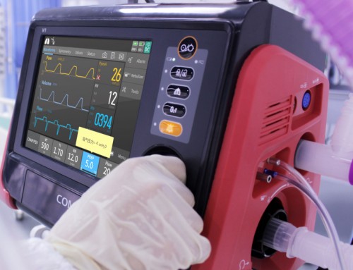
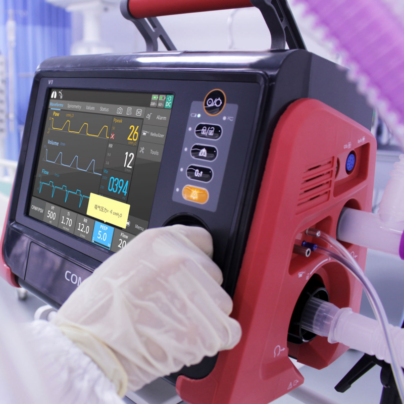
Medical-grade battery packs configured with 18650 cylindrical cells—such as 4S2P or 7S4P architectures used in transport ventilators, infusion pumps, and portable patient monitors—frequently operate under continuous float charge conditions while connected to AC mains power. Over extended periods, subtle divergence in individual cell characteristics leads to severe voltage imbalance across series strings. When an AC mains interruption occurs, a pack with unbalanced series cells experiences premature low-voltage cutoff triggered by the lowest-capacity or highest-impedance cell string. This causes an unexpected system shutdown long before the fuel gauge’s calculated state-of-charge (SOC) reaches zero. Implementing precise 18650 cell balancing techniques within the Battery Management System (BMS) is essential to maintain pack capacity, prevent localized overcharging, and guarantee predictable backup runtime in life-critical medical devices.
Cell Imbalance Dynamics in Multi-Series Medical Battery Packs
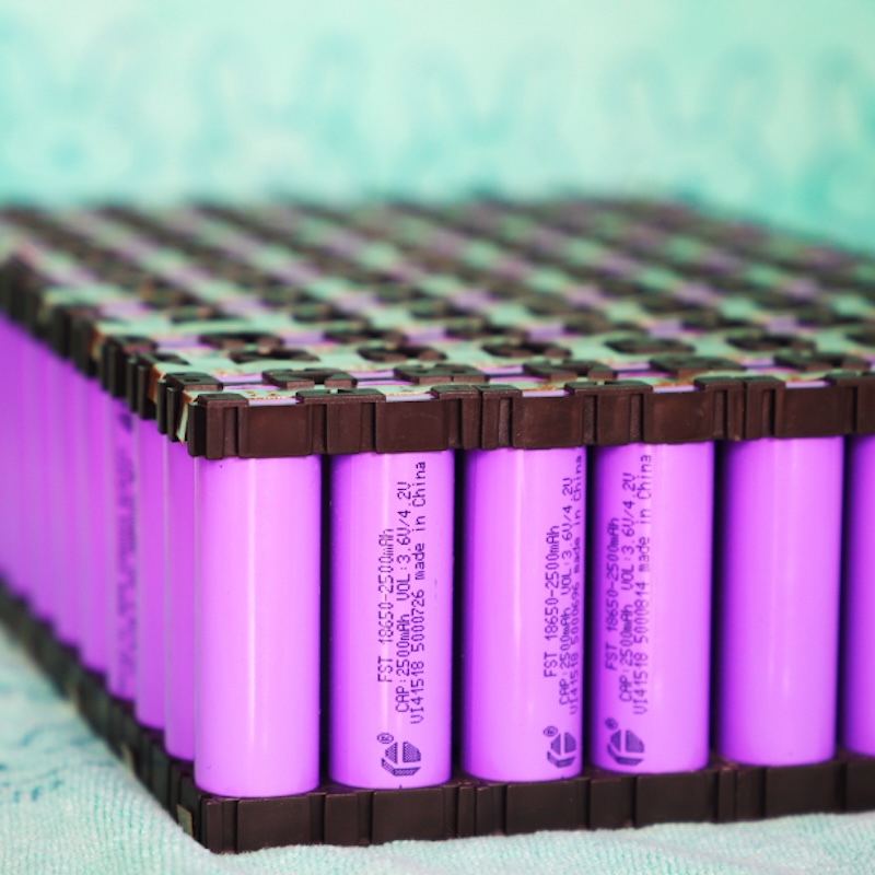
Multi-series 18650 battery packs undergo progressive cell divergence driven by both internal manufacturing tolerances and external thermal gradients within medical device enclosures. Even high-grade tier-1 18650 cells exhibit initial capacity variations up to $\pm 1.5\%$ and slight differences in equivalent direct-current internal resistance ($R_{\text{DC}}$). When connected in series, the exact same charge and discharge current flows through every cell, but cells with lower capacity or higher internal resistance experience higher voltage swings during dynamic load cycles.
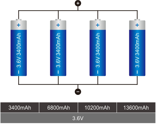
During long-term continuous float charging at $4.20\text{ V}$ per cell, cells with higher self-discharge rates gradually lose charge relative to adjacent cells. Conversely, cells with slightly higher internal impedance reach their upper voltage cutoff threshold earlier during the Constant Current (CC) charge phase, forcing the BMS to transition to the Constant Voltage (CV) phase prematurely. Over hundreds of float-charge days, this divergence degrades the total usable pack energy. Without corrective balancing, the usable capacity of the battery pack becomes constrained by the highest-voltage cell during charging and the lowest-voltage cell during discharging.
Mechanisms of Capacity Drift and Impedance Growth
Imbalance manifests primarily through two distinct mechanisms: SOC mismatch and capacity/impedance mismatch. SOC mismatch occurs when cells possess identical total capacities but differ in their present charge state due to unequal parasitic drain or self-discharge currents. Capacity/impedance mismatch occurs as cells age unevenly. In sealed medical monitor enclosures, non-uniform heat distribution from nearby processing units or power supplies causes cells located closer to heat sources to experience accelerated solid-electrolyte interphase (SEI) layer growth. This localized thermal degradation increases $R_{\text{DC}}$ and accelerates permanent capacity loss in specific series strings, amplifying voltage drift during high-current pulse loads.
Passive vs. Active Cell Balancing Topologies for ICU Equipment
Selecting the appropriate cell balancing topology requires balancing system complexity, thermal dissipation limits, and electromagnetic interference (EMI) constraints inherent to critical care environments.
Passive cell balancing remains the predominant topology in medical 18650 battery packs due to its circuit simplicity, low component count, and high operational reliability. Passive balancing operates by bypassing excess charge from higher-voltage cells through bleeding resistors switch-controlled by the BMS field-effect transistors (FETs). The excess energy is dissipated as heat according to $P = I^2 R$. Typical passive balancing currents are configured between $50\text{ mA}$ and $150\text{ mA}$. While highly effective for low-capacity drift, passive balancing is restricted to the top-of-charge phase to prevent unnecessary energy waste during discharge. Furthermore, localized heat dissipation from bleeding resistors must be carefully managed in sealed, IP-rated medical enclosures to avoid raising the ambient temperature of adjacent 18650 cells.

Medical Patient Monitor
Active cell balancing redistributes charge from higher-voltage cells to lower-voltage cells using capacitive, inductive, or transformer-based charge-transfer circuits. Because energy is transferred rather than dissipated, active balancing generates negligible localized heat and can operate continuously during charge, discharge, and idle states at higher balancing currents ($>1\text{ A}$). However, active balancing topologies introduce additional circuit complexity, higher Bill of Materials (BOM) costs, and switching noise.
Thermal Management and EMI Mitigation in Medical BMS Design
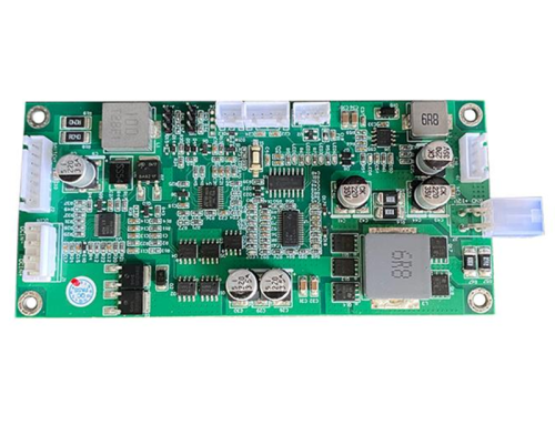
For critical care equipment, thermal control and low electromagnetic noise are mandatory. In passive balancing designs, bleeding resistors should be placed near the outer edge of the BMS printed circuit board (PCB), thermally isolated from sensitive analog sensing traces and the 18650 cell bodies. Thermal vias and copper pour areas are utilized to dissipate heat across the PCB surface. In active balancing designs using inductive switching converters, high-frequency switching noise can couple into sensitive medical instrument front-ends, such as ECG amplification circuits or blood pressure sensor lines. Consequently, active balancing inductors require magnetic shielding, optimized loop areas, and additional LC filtering to comply with IEC 60601-1-2 electromagnetic compatibility standards.
BMS Control Logic and Threshold Configurations
Effective cell balancing relies on precise BMS firmware control algorithms that dictate when, how, and for how long balancing currents are activated.
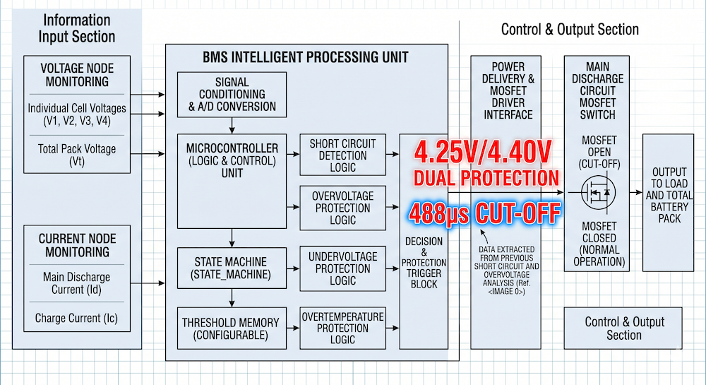
Executing cell balancing based solely on instantaneous voltage measurements during dynamic load conditions leads to false balancing. During motor actuation in ventilators or rapid pump cycles in infusion systems, temporary voltage drops occur due to cell internal resistance ($I \times R_{\text{DC}}$) rather than true SOC divergence. Therefore, robust medical BMS logic restricts cell balancing activation to specific operational windows: during the Constant Voltage (CV) charging phase, or when the pack is in a rested, zero-current state where cell voltages reflect true Open Circuit Voltage (OCV).
Register Configuration in SMBus / I2C Fuel Gauges
Modern medical battery packs utilize integrated fuel gauge ICs communicating over SMBus v1.1 or I2C protocols. Engineers configure specific register parameters within the gauge firmware to manage cell balancing execution:
-
Balancing Activation Threshold Voltage: The minimum cell voltage required before balancing can initiate, typically set near $3.80\text{ V}$ to $4.00\text{ V}$ per cell.
-
Delta-V Activation Window ($\Delta V_{\text{start}}$): The cell-to-cell voltage differential required to trigger balancing, usually set between $10\text{ mV}$ and $20\text{ mV}$.
-
Delta-V Stop Window ($\Delta V_{\text{stop}}$): The differential threshold at which balancing terminates, typically set to $5\text{ mV}$.
-
Temperature Cutoff Limits: The BMS disables balancing if internal temperature sensors detect pack temperatures exceeding $45^\circ\text{C}$ or falling below $0^\circ\text{C}$, preventing thermal escalation during charge management.
Verification Protocols and Integration Standards
Validating cell balancing performance requires rigorous testing under simulated medical operating environments before battery pack integration.
Engineers execute accelerated cycle testing combined with artificially induced cell imbalance (such as introducing a cell string with a $10\%$ lower initial SOC) to evaluate the BMS balancing recovery rate over multiple charge cycles. Infrared thermography is employed during extended passive balancing to confirm that PCB surface temperatures remain within specified limits and do not transmit thermal stress to adjacent 18650 cells.
Compliance Requirements for Medical Secondary Battery Systems
Medical battery packs incorporating 18650 cell arrays must comply with international safety standards including IEC 62133-2 for portable secondary lithium cells and UL 2054 for commercial batteries. The cell balancing circuit serves as a primary control mechanism to satisfy overcharge protection requirements specified in these standards. Preventing cell voltage divergence ensures that individual cells within a series string never exceed the maximum upper charging voltage limit ($4.25\text{ V}$), thereby mitigating lithium plating risks and thermal runaway hazards.
For equipment design teams seeking fully certified power units with pre-configured BMS balancing algorithms and calibrated SMBus fuel gauging, evaluating off-the-shelf medical battery architectures simplifies the compliance process. Explore our technical documentation and engineering specifications for standard battery packs to accelerate your medical device development timeline.