What Does Battery Optimization Mean for B2B Industrial Equipment Engineers?
Field technicians deploying portable spectrum analyzers and medical personnel operating bedside diagnostic monitors frequently encounter power subsystem failures caused by unpredicted voltage cutoffs, localized thermal throttling, or rapid capacity degradation. OEM hardware engineers often treat energy storage as an isolated off-the-shelf component rather than an integrated electrical subsystem. Battery optimization resolves these system-level performance bottlenecks. Rather than simply selecting high-capacity cells, battery optimization aligns the electrochemical, thermal, and electronic parameters of a custom lithium-ion pack directly with the operational duty cycle, environmental conditions, and spatial constraints of host equipment.
What Does Battery Optimization Mean at the Electrochemistry and Cell Architecture Level?
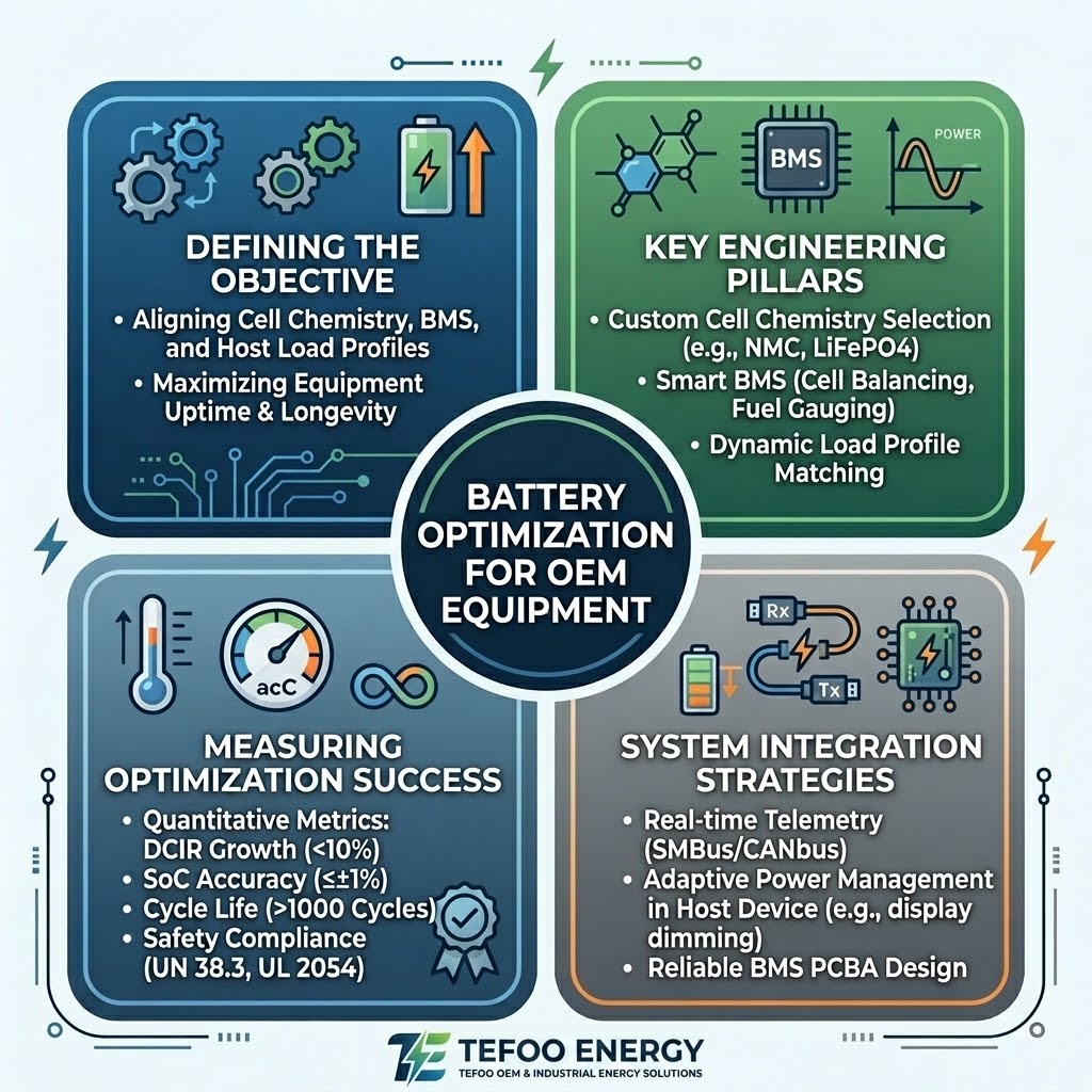
Battery optimization at the electrochemical level means matching lithium cell chemistry selection, physical form factor, protection circuitry, and voltage boundaries directly to host device operating power profiles. Hardware engineers designing portable industrial equipment must select appropriate lithium-ion chemistries and mechanical form factors to ensure baseline electrical efficiency. Unmatched cell selection leads to premature voltage sag under peak discharge loads, excessive internal heat generation, and shortened system cycle life. System-level optimization integrates cell chemistry with Battery Management System (BMS) control algorithms to regulate operational parameters across variable load conditions.
How Does Lithium Cell Chemistry Selection Impact OEM Equipment Performance?
Selecting between nickel manganese cobalt (NMC) 18650 cells and lithium iron phosphate (LiFePO4) 21700 cells establishes nominal voltage, gravimetric energy density, peak discharge rate, and thermal safety limits for the device power subsystem. High-energy NMC chemistry provides nominal cell voltages of 3.6V and energy densities reaching 250 Wh/kg, making NMC ideal for space-constrained medical monitors and compact diagnostic devices. Conversely, LiFePO4 chemistry delivers lower energy density near 160 Wh/kg at a nominal 3.2V, but offers 2,000 to 3,000 charge-discharge cycles alongside high thermal stability up to 60°C. Matching cell discharge capabilities to host peak current draws prevents localized thermal runaway and capacity loss caused by internal impedance growth.
How Does Smart BMS Firmware Execution Control Cell String Voltage Balancing?
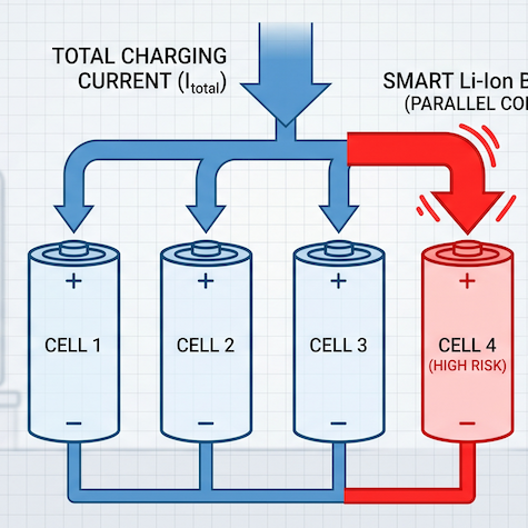
Smart BMS firmware execution utilizes active or passive cell balancing algorithms to equalize voltage across series cell groups, preventing localized overcharging and low-voltage cutoffs. Voltage imbalances naturally develop in multi-cell series strings due to manufacturing tolerances and thermal gradients within the battery enclosure. Integrated fuel gauge ICs running coulometric counting algorithms alongside impedance tracking measure individual cell string voltages to within ±1% State of Charge (SoC) accuracy. Passive balancing topologies bleed off excess energy through dedicated resistor networks at currents between 50 mA and 200 mA during charging cycles, maintaining uniform capacity utilization across all series cell groups.
What Are the Core Engineering Pillars of Battery Optimization in Rugged Applications?
The primary technical pillars of industrial battery optimization consist of dynamic load profile matching, enclosure thermal management, and cycle degradation suppression in harsh operating environments. Operating OEM equipment in unconditioned industrial or clinical environments requires dedicated hardware and firmware mechanisms to mitigate environmental stress factors. Unregulated power draw or unmanaged thermal dissipation leads to solid-electrolyte interphase (SEI) decomposition and internal cell shorting. Integrating real-time sensor networks and adaptive control logic stabilizes battery performance across changing environmental conditions.
How Do Dynamic Load Profiles Influence BMS Over-Current Threshold Design?
Dynamic load profile matching tunes BMS protection timing thresholds to accommodate high transient current surges from motors, pumps, or RF transmitters without triggering false over-current fault shutdowns. Transient inductive current spikes induce immediate voltage drops across the internal direct current resistance (DCIR) of lithium-ion cells. Standard protection circuits with rigid over-current trip delays often trigger false fault trips during high-surge device startup sequences. Adjusting BMS firmware trip timing—combined with localized hardware decoupling capacitors—allows short-duration current surges while preserving microsecond-level short-circuit protection against real external electrical short circuits.
How Does Enclosure Thermal Control Prevent Thermal Degradation in Sealed Batteries?
Thermal control strategy maintains internal lithium cell operational temperatures within the optimal 15°C to 35°C window to prevent accelerated SEI layer growth and destructive lithium plating. Sealed IP67 industrial enclosures inhibit natural convection heat transfer, allowing thermal energy generated during high-rate discharge to accumulate within internal cell clusters. Battery optimization employs passive heat sinks, phase-change thermal interface materials, and optimized cell spacing to eliminate internal hot spots. Multi-point NTC thermistors continuously monitor temperature deltas across the pack; if internal temperatures exceed 45°C during discharge or drop below 0°C during charge, BMS firmware throttles current limits to protect cell structural integrity.
How Do Engineers Measure and Validate Battery Optimization Performance?
Validating battery optimization requires measuring quantitative metrics including internal resistance growth rate, State-of-Charge tracking drift, temperature uniformity, and compliance with international regulatory standards. Evaluating power subsystem performance requires standardized laboratory cycling under simulated duty cycles and environmental conditions. Unoptimized battery designs exhibit rapid capacity decay and unpredictable runtime estimations, whereas optimized architectures maintain stable electrical metrics across extended operating life.
What Quantitative Metrics Differentiate Optimized Battery Architecture from Unoptimized Designs?
Quantitative evaluation comparing unoptimized and optimized battery pack architectures demonstrates significant differences in impedance growth, gauge drift, thermal delta, and operational cycle longevity. Standardized testing under accelerated environmental stress quantifies the measurable benefits of customized BMS control logic and thermal equalization engineering.
| Parameter |
Unoptimized Battery Architecture |
Optimized OEM Battery Architecture |
| DCIR Growth Rate |
>30% increase per 300 cycles |
<10% increase per 500 cycles |
| SoC Gauge Accuracy |
±8% to ±12% uncalibrated drift |
≤±1% accuracy via SMBus Impedance Tracking |
| Cell Temperature Delta |
>8°C variation across series string |
≤3°C variation via thermal equalization |
| Cycle Life (to 80% Capacity) |
300 to 500 total cycles |
1,000 to 2,000+ cycles (chemistry dependent) |
| Low-Temp Charge Protection |
Unprotected charging causes lithium plating |
Current throttling below 0°C via BMS firmware |
Which International Safety Standards Validate Optimized Industrial Battery Packs?
Compliance with international testing standards including IEC 62133-2, UL 2054, and UN 38.3 certifies that an optimized battery pack meets electrical, mechanical, and transport safety requirements. Medical equipment power supplies must pass IEC 62133-2 for portable sealed secondary cells and UL 2054 for commercial battery packs, verifying overcharge, external short-circuit, and mechanical shock resistance. Hazardous material transportation mandates compliance with UN 38.3, subjecting battery assemblies to altitude simulation, thermal shock, vibration, and forced discharge testing. Integrating compliance requirements early in the hardware design phase avoids redesign delays during final product certification.
How Do Communication Protocols and System Architecture Implement Real-Time Optimization?
Real-time battery optimization relies on communication protocols such as SMBus v1.1 and CAN 2.0B to stream real-time operational telemetry between the battery pack BMS and the host equipment main controller. Connecting the power subsystem to the primary host device microprocessor transforms the battery pack into an active participant in system energy management. Embedded communication protocols continuously broadcast critical health parameters, allowing host system firmware to adaptively adjust device operation based on remaining power reserves.
How Does Telemetry Streaming Enable Adaptive Host Power Management?
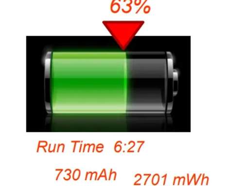
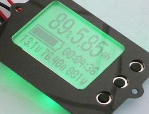
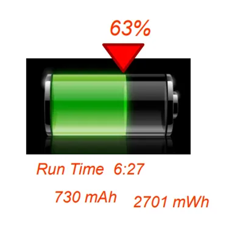
Telemetry streaming over SMBus or CANbus enables host equipment firmware to trigger dynamic power-saving modes, such as display dimming or clock frequency throttling, based on real-time State-of-Charge and temperature data. Smart battery packs transmit real-time data packets containing terminal voltage, individual cell string voltages, current draw, State-of-Charge (SoC), State-of-Health (SoH), and NTC thermistor temperatures. Host equipment microprocessors process these data streams to initiate predictive software actions, such as saving active patient logs or gracefully powering down non-critical peripherals before low-voltage shutdown thresholds are reached.
What Hardware Design Standards Ensure Secure BMS PCBA Integration on Host Equipment?
Hardware design standards require high-side MOSFET switching, shielded bus lines, and dedicated gas gauge IC placement to eliminate ground offsets and prevent communication failure during high-current transient events. Designing the Printed Circuit Board Assembly (PCBA) for an optimized BMS requires isolating low-voltage communication traces from high-current power paths. Implementing high-side N-channel MOSFET switches maintains a continuous system ground reference between the battery pack and host equipment, eliminating ground bounce that corrupts SMBus data packets. Dedicated hardware protection ICs provide secondary over-voltage protection independent of primary BMS firmware execution, guaranteeing redundant hardware safety.
Frequently Asked Questions
What does battery optimization mean in B2B OEM equipment design?
Battery optimization in OEM equipment design means matching lithium cell chemistry, BMS control logic, thermal management, and communication protocols directly to host device operating requirements.
How does smart BMS firmware extend lithium-ion battery operational lifespan?
Smart BMS firmware extends lifespan by performing cell voltage balancing, enforcing temperature-based charging limits, and preventing over-discharge through real-time coulometric monitoring.
Why is SMBus communication critical for optimized medical device battery packs?
SMBus communication transmits real-time State-of-Charge, State-of-Health, and temperature telemetry to host device microprocessors, enabling dynamic system power management and graceful shutdowns.
How does thermal management affect battery pack performance in IP67 sealed housings?
Thermal management prevents heat accumulation inside sealed IP67 housings using thermal interface materials and heat spreaders, maintaining cell temperatures within 15°C to 35°C to prevent rapid capacity degradation.
What international safety standards validate custom industrial battery pack optimization?
Custom industrial battery packs are validated through IEC 62133-2 for safety, UL 2054 for commercial durability, and UN 38.3 for transport testing under altitude, shock, and vibration stresses.