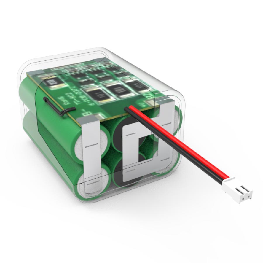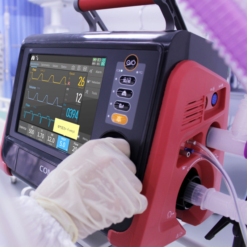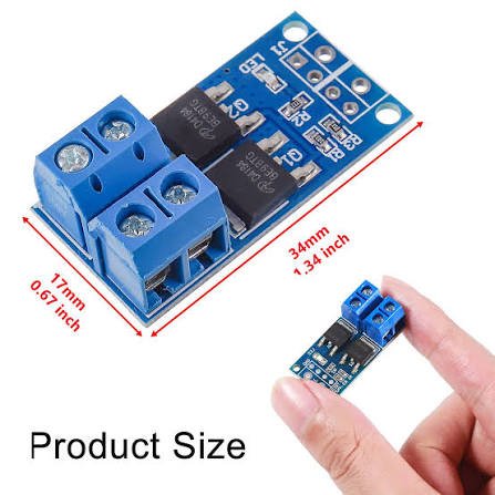
Transient overvoltage spikes, unmitigated short-circuit discharge, and localized thermal divergence in multi-cell packs directly compromise operational safety and accelerate capacity degradation in industrial equipment. Implementing robust lithium-ion battery protection requires integrating dedicated hardware protection ICs, dual-switching N-channel MOSFETs, Negative Temperature Coefficient (NTC) thermistors, and intelligent control algorithms. A well-engineered safety architecture maintains individual cell voltages within electrochemical stability limits, isolates thermal anomalies, and guarantees continuous power delivery across demanding industrial operating environments.
[Key Takeaways]
-
Voltage and Current Cutoffs: Dedicated protection ICs isolate charging circuits at 4.25 V to 4.40 V per cell and disconnect load circuits at 2.30 V to 2.75 V per cell, while ultra-fast MOSFETs halt short-circuit currents within microsecond response windows.
-
Thermal Isolation Thresholds: NTC thermistor arrays inhibit battery charging outside 0 °C to 45 °C (32 °F to 113 °F) and enforce hard discharge shutdowns between 60 °C and 90 °C (140 °F to 194 °F) to prevent thermal runaway.
-
Topology Selection and Compliance: High-reliability industrial systems require choosing between standalone Protection Circuit Modules (PCM) and fully managed Battery Management Systems (BMS), validated through UN 38.3, IEC 62133, and UL 2054 testing frameworks.
What Hardware Mechanisms Prevent Overvoltage and Overcurrent Failures in Lithium-Ion Battery Protection?
Electric overstress mitigation relies on integrated protection circuits that continuously monitor individual series cell voltages and discharge current rates against pre-programmed physical thresholds.
Overcharge and Over-Discharge Voltage Threshold Calibration
Integrated protection ICs cut off charge currents when individual cell voltages exceed 4.25 V to 4.40 V and isolate connected loads when cell voltages drop below 2.30 V to 2.75 V to eliminate internal electrode degradation and thermal runaway risks. Lithium-ion cell chemistries, such as Nickel Manganese Cobalt (NMC) and Lithium Iron Phosphate (LFP), exhibit narrow voltage stability windows. Exceeding 4.40 V per cell causes electrolyte oxidation and metallic lithium plating on the graphite anode, triggering thermal instability. Conversely, discharging below 2.30 V causes copper current collector dissolution, leading to internal short circuits during subsequent recharge cycles. Protection ICs continuously compare analog cell tap inputs against internal reference voltages, instantly signaling high-side or low-side switching transistors to open the circuit whenever voltage thresholds are breached.
Precision voltage monitoring prevents chemical decomposition and maintains structural cell integrity over thousands of operational cycles.
Short-Circuit and Overcurrent Disconnect Response Protocols
Low internal resistance switching MOSFETs interrupt transient overcurrent and short-circuit faults within 10 to 500 microseconds to protect internal busbars and external device electronics. During a direct terminal short circuit, discharge currents escalate rapidly, causing severe I²R ohmic heating across conductive nickel strips and cell interconnects. Current sensing resistors placed in series with the negative power line generate a proportional millivolt drop that the protection IC evaluates. If the voltage drop indicates an current draw above the rated maximum continuous discharge specification, the gate drive voltage to the discharge MOSFET drops to zero, terminating current flow instantly.
| Protection Parameter | Electrical / Physical Threshold | Response Time / Tolerance | Engineering Standard Benchmark |
| Overcharge Cutoff Voltage | 4.25 V to 4.40 V per cell | ±25 mV tolerance |
IEC 62133 / UL 2054
|
| Over-Discharge Cutoff Voltage | 2.30 V to 2.75 V per cell | ±50 mV tolerance |
UN 38.3 / IEC 62133
|
| Short-Circuit Current Delay | 200 A to 800 A peak surge | 10 µs to 500 µs response |
UL 2054 Section 13
|
| Cell Balancing Voltage Delta | 10 mV to 30 mV inter-cell variance | Active/Passive current shunt |
IEEE 1725 / BMS Specification
|
Fast-acting overcurrent cutoffs shield the battery pack internal interconnects and external load circuits from catastrophic thermal damage.
How Does Thermal Architecture Mitigate Degradation and Thermal Runaway in Industrial Lithium-Ion Battery Protection?
Thermal protection relies on real-time temperature tracking via strategically placed thermistors combined with flame-retardant structural materials to isolate heat generation.
NTC Thermistor Placement and Temperature Window Regulation
NTC thermistors strategically attached to central cell bodies prohibit charging operations outside 0 °C to 45 °C (32 °F to 113 °F) and initiate hard load cutoffs when internal temperatures reach 60 °C to 90 °C (140 °F to 194 °F). Temperature fluctuations significantly alter lithium-ion transport kinetics within the electrolyte. Charging below 0 °C (32 °F) dramatically increases internal cell impedance, causing dendrite growth that can puncture the separator. Discharging above 45 °C (113 °F) accelerates solid-electrolyte interphase (SEI) layer growth, increasing internal resistance. Thermal sensing circuits monitor resistance changes in 10kΩ NTC sensors positioned at the thermal core of the cell array. When measured values fall outside pre-calibrated safety windows, the control IC opens the charging or discharging FET switches until temperature equilibrium is restored.
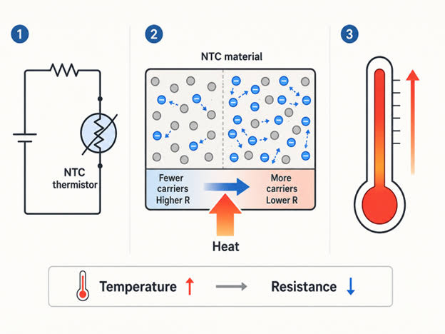
Strict enforcement of thermal operating boundaries suppresses thermal degradation mechanisms and prevents catastrophic cell venting.
Cell Isolation and Thermal Interface Material Integration
Integrating flame-retardant PC/ABS brackets with 1.5 mm (0.059 in) cell-to-cell spacing and polyurethane thermal interface materials (1.2 W/m·K) prevents cascade propagation during localized thermal events. Matrix brackets constructed from UL94 V-0 rated polycarbonate/acrylonitrile butadiene styrene (PC/ABS) provide mechanical isolation and structural damping against severe industrial shock and vibration. Filling module air gaps with high-conductivity thermal pads or gap fillers dissipates localized heat evenly toward external heat sinks or metal enclosures. Electrical isolation is reinforced using heat-resistant Polyimide (Kapton) tape (dielectric strength > 5 kV) and heat-shrink sleeving across all exposed busbar connections.
B2B Engineering Note: For specialized OEM industrial equipment requiring robust lithium-ion battery protection, engineering teams should evaluate custom battery pack solutions featuring tailored BMS firmware, direct-welded pure nickel interconnects, and IP67 potting encapsulation to withstand corrosive and high-humidity environments.
Combining physical cell isolation with thermal interface materials prevents single-cell thermal failures from propagating across the entire battery module.
How Do PCM, PCB, and BMS Topologies Differ for B2B Lithium-Ion Battery Protection Procurement?
Selecting the appropriate protection architecture depends on system voltage, cell series count, communication requirements, and total cost of ownership (TCO) constraints.
Topology Architectural Differences and Functional Scopes
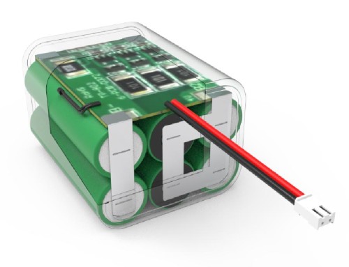
Protection Circuit Modules (PCM) provide fundamental analog hardware cutoffs for simple cell arrays, whereas digital Battery Management Systems (BMS) deliver active state-of-charge (SOC) calculation, health monitoring, and system bus communication. PCMs rely on fixed-threshold comparator ICs and power MOSFETs to deliver low-cost, plug-and-play safety for single-cell or low-voltage series packs (1S to 4S). Conversely, a full BMS incorporates a dedicated microcontroller unit (MCU), digital fuel gauge ICs, and active or passive cell balancing circuitry. System-level communication interfaces—such as System Management Bus (SMBus), Controller Area Network (CAN bus 2.0B), or RS485—allow the BMS to transmit real-time telemetry (cell voltages, pack current, state of health, temperature profiles) directly to the host equipment’s primary system controller.
| Feature / Metric | Protection Circuit Module (PCM) | Printed Circuit Board Protection (PCB) | Battery Management System (BMS) |
| Primary Control Architecture |
Analog Hardware Comparators
|
Integrated Analog Protection ICs
|
Microcontroller (MCU) + Digital Firmware
|
| Series Cell Capacity Range |
1S to 4S Cells
|
1S to 10S Cells
|
3S to 240S+ High-Voltage Arrays
|
| Data Communication Protocols |
None (Standalone hardware)
|
Optional UART / Simple Status I/O
|
CAN bus, SMBus, Modbus RS485, I²C
|
| Cell Balancing Capabilities |
None or Basic Passive Shunting
|
Basic Passive Balancing
|
Active / Advanced Passive Balancing
|
| Relative TCO & Unit Cost |
Lowest Initial Procurement Cost
|
Moderate Cost / Low Complexity
|
Higher Initial Cost / Lowest Field Risk
|
Determining the proper control topology balances upfront hardware expense against the required degree of real-time telemetry and battery pack intelligence.
Compliance Verification with Global Battery Safety Standards
Industrial-grade battery systems require mandatory compliance testing under UN 38.3, IEC 62133, and UL 2054 to certify electrical fault resistance and transport safety. Transport regulations (UN 38.3) subject fully assembled packs to thermal altitude simulation, vibration, mechanical shock, external short circuit, and impact tests. Equipment safety standards, such as IEC 62133-2 (for portable lithium systems) and UL 2054 (for commercial batteries), require rigorous fault-condition testing—including single-fault component failures, forced internal short circuits, and abnormal charging conditions—without explosion or fire.
Procurement Guidance: Industrial procurement managers specifying custom battery pack solutions should confirm that protection circuit layouts adhere to IPC-2221 creepage and clearance specifications, incorporate high-current copper trace weights (≥ 2 oz/ft²), and possess pre-certified UN 38.3 documentation to minimize compliance timelines and field liability.
Rigorous third-party certification validates that the hardware protection architecture reliably mitigates extreme electrical, thermal, and mechanical stress in field operations.