A battery in an electrical circuit functions as an active direct current (DC) power transducer that converts stored electrochemical potential energy into electrical energy, establishing an electromotive force (EMF) across its output terminals. In industrial automation, uninterruptible power supply (UPS) units, and automated guided vehicles (AGVs), the battery acts as a non-conservative voltage source that drives charge carriers (electrons) through resistive, inductive, and capacitive loads while maintaining system operating voltage within defined limits. Understanding how chemical energy conversion, internal resistance ($R_i$), and series-parallel matrix topologies interact is essential for optimizing power system efficiency, managing dynamic load profiles, and extending industrial equipment lifecycles.
[Key Takeaways]
-
Electromotive Force Generation: A battery establishes an electrical potential difference ($E$) across a closed loop, converting chemical energy into electrical energy to maintain steady electron drift velocity under dynamic loads.
-
Voltage Regulation and Impedance Control: Terminal voltage ($V_{term}$) fluctuates relative to open-circuit voltage ($OCV$) based on internal cell resistance ($R_i$), requiring engineered current pathways and cell sorting to minimize Ohmic losses.
-
Industrial Chemistry Performance: Modern Lithium Iron Phosphate ($\text{LiFePO}_4$) systems deliver 98% charge efficiency and 3,500 cycles at 80% Depth of Discharge (DoD), drastically outperforming legacy lead-acid systems in total cost of ownership.
How Does a Battery Function as an Electromotive Force Source in a DC Circuit?
Electrochemical Energy Conversion and Current Flow Dynamics
A battery converts internal electrochemical free energy into electrical work by maintaining a constant potential difference across its positive and negative terminals, forcing free electrons through an external load circuit. When a conductive circuit loop closes, spontaneous oxidation reactions at the anode release electrons, while reduction reactions at the cathode consume incoming electrons. The liquid or solid electrolyte facilitates ionic charge transport inside the cell casing to maintain charge neutrality. According to Ohm’s law, the continuous direct current ($I$) circulating through the load is defined by:
$$I = \frac{E}{R_{ext} + R_i}$$
where $E$ represents the internal electromotive force in volts (V), $R_{ext}$ is the external load resistance in ohms ($\Omega$), and $R_i$ is the total internal impedance of the cell in ohms ($\Omega$).
-
Anode Oxidation: Releases free electrons to the external circuit during discharge, generating positive ions that migrate through the electrolyte interface.
-
Cathode Reduction: Accepts returning electrons from the load circuit, reducing chemical species at the positive terminal interface.
-
Electrolyte Ionic Transport: Drives internal cation and anion diffusion, completing the internal conduction path without permitting direct electron flow through the separator.
-
Electron Drift Velocity: Maintains steady current flow across conductors without depleting terminal potential during normal operating cycles.
Therefore, the fundamental physical role of the battery is to serve as an active energy transducer that drives continuous electrical charge around a closed circuit loop.
Terminal Voltage Behavior and Internal Resistance Impacts
Terminal voltage ($V_{term}$) deviates from the ideal open-circuit voltage ($OCV$) during operation due to internal Ohmic resistance and electrochemical polarization losses within the battery. When an external load draws current, internal resistance causes an internal voltage drop ($I \cdot R_i$), resulting in the characteristic terminal voltage equation during discharge:
$$V_{term} = E – I \cdot R_i$$
Conversely, during charging operations, the applied circuit voltage must overcome this internal impedance ($V_{term} = E + I \cdot R_i$). Total internal resistance comprises Ohmic resistance ($R_{\Omega}$) from current collector foils, tab welds, and electrolyte resistance, alongside charge transfer resistance ($R_{ct}$) and mass transfer diffusion impedance ($R_d$). High internal resistance causes excessive $I^2 R$ heat generation, reducing system efficiency and lowering usable discharge capacity under high C-rate requirements.
| Battery Chemistry | Nominal Voltage (V) | Operating Range (V) | Typical Internal Resistance (mΩ) | Charge Efficiency (%) | Cycle Life (80% DoD) | Volumetric Energy Density |
| Lithium Iron Phosphate ($\text{LiFePO}_4$) | 3.2 V | 2.50 V – 3.65 V | 0.5 $m\Omega$ – 2.0 $m\Omega$ | 98% | 3,500 cycles |
270 Wh/L (16.5 $\text{Wh/in}^3$)
|
| Nickel Manganese Cobalt (NMC) | 3.6 V – 3.7 V | 2.75 V – 4.20 V | 1.0 $m\Omega$ – 3.5 $m\Omega$ | 95% – 97% | 1,500 – 2,000 cycles | 450 – 600 Wh/L (27.5 – 36.6 $\text{Wh/in}^3$) |
| Valve-Regulated Lead-Acid (VRLA) | 2.0 V/cell | 1.75 V – 2.40 V | 5.0 $m\Omega$ – 15.0 $m\Omega$ | 80% – 85% | 500 – 800 cycles |
80 Wh/L (4.9 $\text{Wh/in}^3$)
|
| Nickel-Metal Hydride (NiMH) | 1.2 V | 1.00 V – 1.45 V | 10.0 $m\Omega$ – 25.0 $m\Omega$ | 70% – 75% | 500 – 1,000 cycles |
180 – 300 Wh/L (11.0 – 18.3 $\text{Wh/in}^3$)
|
Quantifying internal resistance and selecting low-impedance cell chemistries enables battery engineers to stabilize terminal voltage output across variable industrial load demands.
How Do Series and Parallel Topologies Alter Battery Circuit Characteristics?
Series Cell Topologies for High-Voltage Industrial Demands
Connecting individual battery cells in a series configuration increases total system output voltage while keeping the circuit current throughput identical across all cells. The total electromotive force ($E_{total}$) of $n$ cells connected positive-to-negative equals the sum of individual cell electromotive forces ($E_1 + E_2 + … + E_n$). Higher circuit voltages allow industrial equipment, such as 48 V forklifts or 384 V UPS backup systems, to deliver substantial electrical power ($P = V \cdot I$) at lower operating currents, minimizing resistive heating ($I^2 R$) in copper wiring harnesses.
-
Voltage Summation: Total voltage scales linearly ($V_{total} = \sum V_{cell}$), satisfying high-voltage industrial motor drive and inverter requirements.
-
Current Uniformity: String current remains constant throughout every series cell, making overall pack performance dependent on the lowest-capacity cell in the string.
-
Compounded Impedance: Series connection adds individual internal resistances ($R_{total} = \sum R_i$), increasing cumulative voltage drop during peak current discharge.
-
Reverse Polarity Risk: Unbalanced series cells risk being driven into reverse polarity by stronger neighboring cells when discharged below threshold limits.
Consequently, series circuit configurations allow efficient power transmission across heavy-duty industrial platforms when supported by strict cell capacity matching.
Parallel Cell Topologies for Expanded Ampere-Hour Storage
Connecting battery cells in a parallel topology multiplies total system capacity and continuous current capability while maintaining the nominal voltage of a single cell. Connecting positive terminals to positive busbars and negative terminals to negative busbars increases total charge capacity ($C_{total} = \sum C_{cell}$) in Ampere-hours (Ah). Furthermore, connecting $m$ identical cells in parallel reduces aggregate internal resistance ($1/R_{total} = \sum 1/R_i$), allowing the battery pack to supply high surge currents without experiencing significant voltage sag.
-
Capacity Scaling: Ampere-hour rating scales directly with cell count, extending equipment runtime without exceeding downstream voltage tolerances.
-
Impedance Reduction: Aggregate pack resistance decreases inversely with parallel cell count, minimizing internal thermal dissipation during power draws.
-
Current Distribution: Total discharge current splits across parallel branches inversely proportional to branch impedance, requiring equalized busbar interconnect resistance.
-
Circulating Current Dynamics: Voltage differentials between parallel cells trigger self-balancing cross-currents, necessitating precise open-circuit voltage sorting prior to module assembly.
Parallel topologies enable procurement managers and system designers to extend industrial runtime without exceeding maximum operating voltage limits of connected power electronics.
Why Is Integrated Battery Protection Essential for Circuit Stability?
Overvoltage, Overcurrent, and Over-Discharge Protection Mechanisms
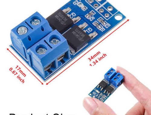
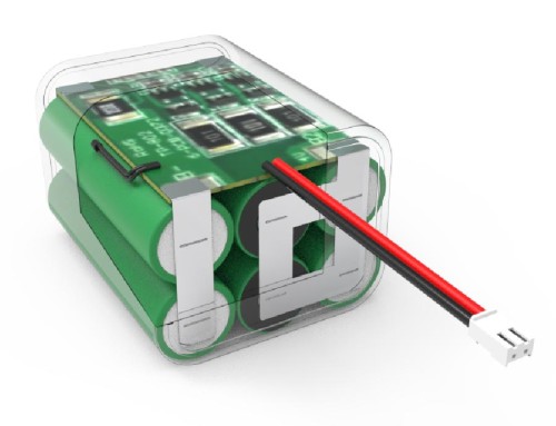
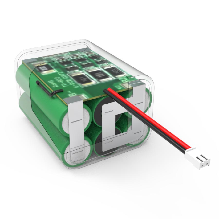
Integrated Protection Circuit Modules (PCM) maintain electrical circuit stability by using solid-state switches to isolate the battery whenever voltage, current, or temperature thresholds exceed safe operational limits. In lithium-ion battery packs, charging individual cells beyond 4.20 V induces electrolyte decomposition and severe overheating, potentially triggering thermal runaway. Discharging cells below 2.50 V causes copper current collector dissolution, creating internal short circuits upon subsequent recharge cycles. High-side or low-side switching power MOSFETs driven by dedicated protection ICs disconnect the circuit in microseconds during short-circuit faults or overcurrent events.
-
Overcharge Cutoff: Disconnects the charging source when cell voltage reaches 4.20 V – 4.35 V, preventing gas generation and cathode degradation.
-
Over-Discharge Cutoff: Opens the load circuit when cell voltage drops to 2.30 V – 2.50 V, preserving internal electrode structure.
-
Short-Circuit Interrupt: Detects high-voltage drops across current sensing shunts, terminating current flow within 10 $\mu s$ to 500 $\mu s$.
-
Reverse Polarity Safeguard: Prevents current flow if installation mistakes reverse positive and negative terminal connections, shielding downstream equipment.
B2B Engineering Conversion CTA: For specialized industrial applications requiring high-reliability custom battery pack solutions, integrating direct-welded pure nickel busbars, tailored BMS firmware, and IP67-rated encapsulation ensures seamless circuit protection under extreme operating conditions.
Incorporating automated circuit protection guarantees that the battery operates exclusively within its electrochemical stability window, preventing premature pack failure and safety hazards.
Thermal Management and State-of-Charge Balancing in Multi-Cell Arrays
Intelligent Battery Management Systems (BMS) utilize thermal management circuits and cell balancing equalizers to preserve capacity uniformity and suppress thermal divergence across multi-cell packs. Cell capacity variance causes weak cells in series strings to charge and discharge faster than adjacent cells, leading to localized overcharging or over-discharging. Passive balancing circuits bleed excess charge from high-voltage cells through resistive shunts, while active balancing circuits redistribute energy from higher-charged cells to lower-charged cells using inductive or capacitive energy transfer. Furthermore, Negative Temperature Coefficient (NTC) thermistor arrays monitor module surface temperatures, triggering thermal cutoffs if temperatures exceed safe discharge limits ($>60\text{ }^\circ\text{C} / 140\text{ }^\circ\text{F}$) or fall below safe charge limits ($<0\text{ }^\circ\text{C} / 32\text{ }^\circ\text{F}$).
| Performance & TCO Metric | Traditional VRLA Lead-Acid UPS | Custom LiFePO4 Energy Storage System | Procurement & TCO Advantage |
| Initial Capital Expenditure (CapEx) | Low initial baseline ($1.0\times$) | Moderate initial investment ($2.2\times$) |
Higher initial cost offset within 24–36 months
|
| Operating Expense (OpEx) / 10 Yrs | High due to replacements & HVAC | Low due to high efficiency & wide temp range |
Up to 60% reduction in long-term operational expense
|
| Service Life & Cycle Count |
500 – 800 cycles @ 80% DoD
|
3,500+ cycles @ 80% DoD
|
Over $4\times$ longer operational service life
|
| Charge Round-Trip Efficiency |
80% – 85% efficiency
|
98% efficiency
|
Reduces active grid power draw during recharge
|
| Scheduled Maintenance Requirement | Monthly capacity & fluid checks | Zero routine chemical maintenance |
Saves up to $18,000 per remote telecom site
|
| System Volumetric Footprint |
80 Wh/L (4.9 $\text{Wh/in}^3$)
|
270 Wh/L (16.5 $\text{Wh/in}^3$)
|
Requires 70% less rack volume in control cabinets
|
B2B Procurement Guidance CTA: Engineering procurement managers specifying mission-critical power systems should evaluate custom battery pack solutions that incorporate active BMS telemetry, custom wiring harnesses, and UN 38.3/IEC 62133 compliant safety architectures.
Deploying continuous cell balancing alongside proactive thermal monitoring prevents localized cell degradation, ensuring predictable power delivery and lowering total cost of ownership in B2B energy applications.