When designing portable medical devices or industrial instruments, hardware teams frequently face a fundamental question regarding power management: How do we safely calculate the maximum charging current for a multi-cell battery pack?
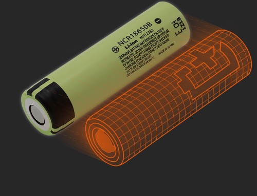
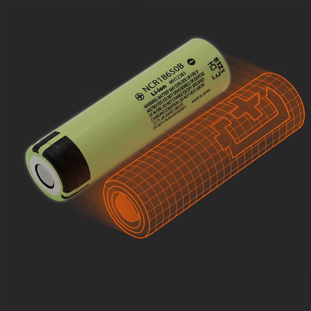
A common discussion on engineering forums like Stack Exchange goes like this: “If my single 18650 cell has a recommended standard charge current of 0.5A, and I put 5 cells in parallel (5P), can I simply set my maximum charging current to 5 × 0.5A = 2.5A?”
Theoretical Foundation of Parallel Diversion and Battery Cell Misconceptions
While the math behind parallel current distribution makes sense on paper, determining the actual safe charging boundary for an OEM device involves more than simple multiplication.
-
Standard vs. Maximum: Standard charge (typically ~0.2C) maximizes cycle life, while maximum charge represents the physical limit for fast charging.
-
Application Fit: Unless fast charging is a strict requirement, designing around the standard charge current provides a gentler operating environment and extends the equipment’s field life.
Why can’t the theoretical value be achieved?
In mass production and field operations, we deal with complex physical variables rather than idealized circuit simulations. Two primary real-world factors dictate why charging currents must leave a reasonable engineering margin.
-
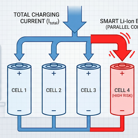
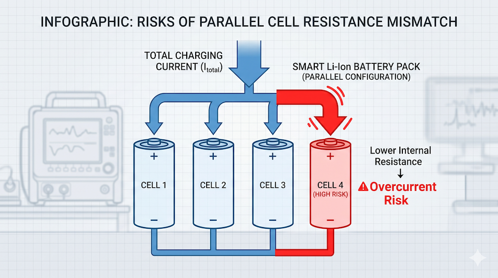
Cell Imbalance and the ‘Funnel’ Effect: Even cells from the same production batch possess minor variances in internal resistance (IR) and capacity. As the pack ages, these differences widen. During high-current charging, the cell with slightly lower resistance will naturally draw a disproportionate share of the current, accelerating its degradation and creating localized thermal risks. This underscores the necessity of precise cell grading and sorting during manufacturing.
-
Thermal Accumulation in Sealed Enclosures: Charging is an exothermic chemical reaction where heat generation scales with the square of the current. In compact, sealed enclosures typical of medical tablets or industrial detectors, internal airflow is restricted. Pushing charging currents to the physical limit can cause internal heat to build up rapidly, triggering premature thermal protection shutoffs and reducing overall charging efficiency.
BMS Oversight and Smart Communication Protocols

Regardless of theoretical cell capabilities, the actual maximum current allowed into a battery pack is governed by the Battery Management System (BMS) and its Charge Overcurrent Protection (OCC) thresholds.
-
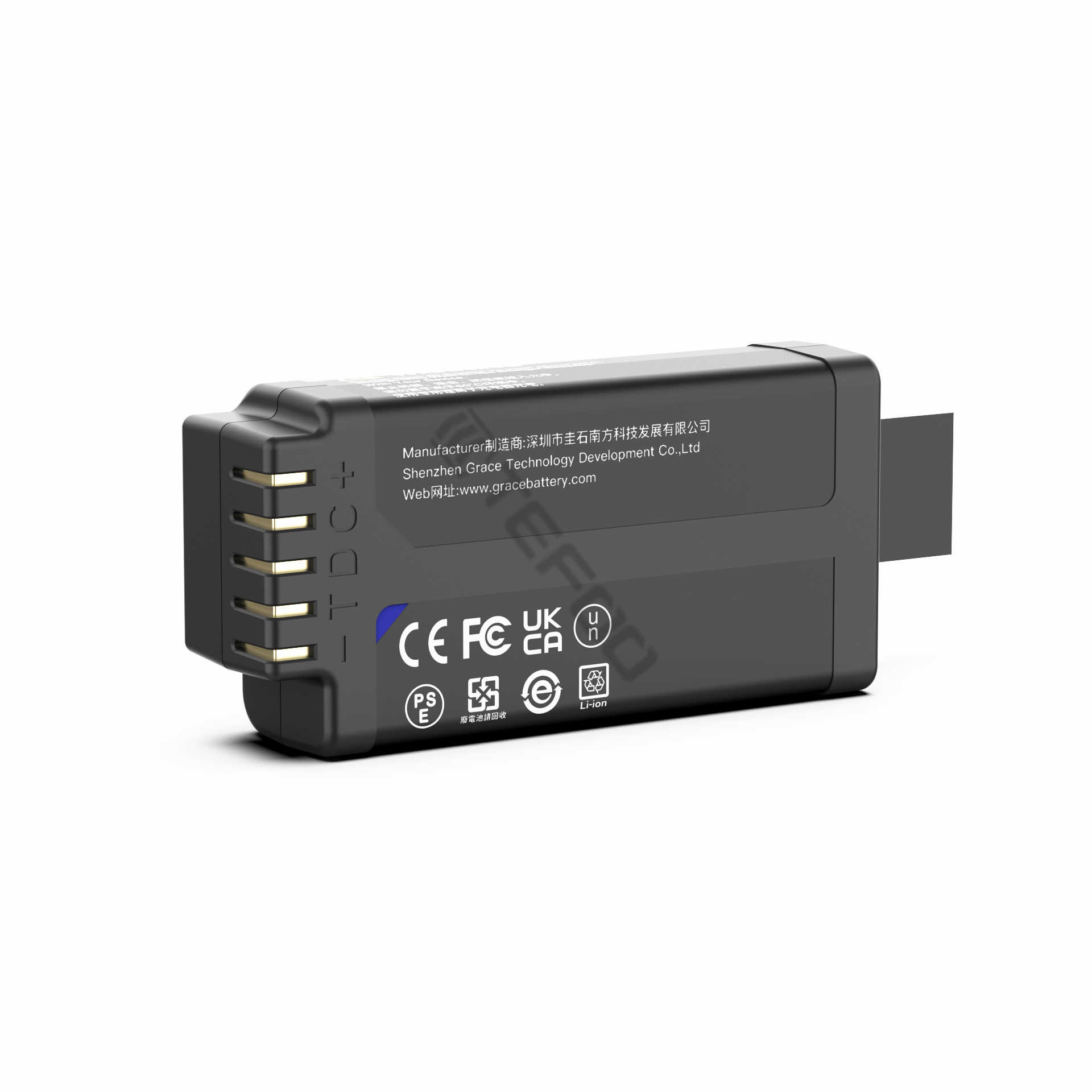
Hardware Safeguards: In high-quality standardized smart battery packs, the OCC threshold is matched precisely to the device’s safety requirements and adapter power, incorporating strict tolerances to prevent damage.
-
Dynamic SMBus Scheduling: A more advanced approach involves smart battery packs utilizing communication protocols like SMBus. Instead of waiting for a hardware overcurrent trip, the internal fuel gauge dynamically broadcasts charging current and voltage requests to the host controller based on real-time cell temperature, age, and state of charge. This allows the system to throttle current smoothly, ensuring a more resilient power architecture.
Finding the Right Balance for Your Project
Ultimately, configuring the charge current is a balancing act between charging speed, thermal management, and battery longevity. For many OEM manufacturers, building and validating custom charging topologies can significantly extend time-to-market. Integrating pre-certified, standardized smart lithium battery modules provides a highly reliable shortcut, as the internal BMS parameters are already optimized and verified against international safety standards like IEC62133 and UN38.3.
FAQ
Q: Can we shorten charging time simply by upgrading to a higher-wattage power adapter?
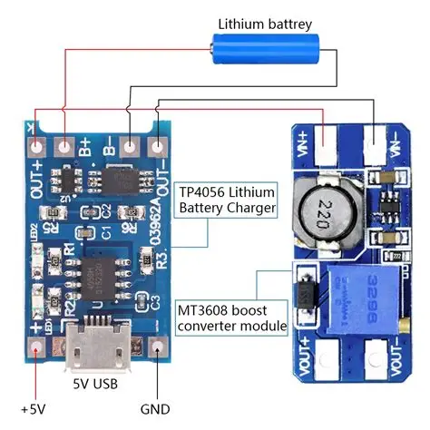
A: Not necessarily. The battery pack’s internal BMS enforces a strict upper limit on charging current. If the input current exceeds the BMS overcurrent protection threshold, the pack will cut off the input entirely. Accelerating charge times requires a synchronized evaluation of the adapter, the device charging circuit, and the battery BMS.
Q: Does adding cells in a series configuration change the charging current calculation?
A: No. Adding cells in series (S) increases the total voltage of the battery pack, but the current flowing through the series chain remains limited by the capacity and parallel (P) configuration of the individual cell groups.
Q: How do we determine the best charging parameters for a new instrument design?
A: The evaluation should start with your target charge time, thermal dissipation budget, and operating temperature range. Our engineering team specializes in both standard smart modules and custom battery integration, providing full support from initial feasibility to SMBus communication tuning. Contact us to discuss your project requirements.