Li Ion Battery Cell Voltage Optimization in Medical Equipment Engineering
Medical device original equipment manufacturers (OEMs) and R&D engineers designing portable patient monitors, infusion pumps, and medical ventilators face strict input voltage window requirements for internal DC-DC converters. Miscalculating li ion battery cell voltage boundaries causes inaccurate State of Charge (SOC) fuel gauge readings, unexpected low-voltage system shutoffs, or accelerated cell degradation during constant-voltage charging phases. Establishing precise nominal voltage platforms, lower discharge cutoffs, and upper overcharge thresholds ensures operational reliability, maximizes battery cycle life, and guarantees compliance with international medical safety regulations.
Nominal vs Peak Limits: Defining Li Ion Battery Cell Voltage Parameters
Li ion battery cell voltage typically operates within a defined window between a 2.75V or 3.00V discharge cutoff threshold and a 4.20V maximum charge limit, with a standard nominal platform of 3.6V or 3.7V per cell. Engineering power management circuits requires accounting for this operational voltage swing to prevent premature system power down under load.
Nominal 3.6V vs 3.7V Cell Voltage Characteristics in NMC Chemistries
Lithium Nickel Manganese Cobalt Oxide (NMC) cells operate at a nominal 3.6V or 3.7V voltage platform determined by cathode chemistry composition and electrochemical potential. Cylindrical 18650 and 21700 cells utilize this nominal rating as a standard baseline for power calculation; for example, a standard 3.7V 2200mAh 18650 cell yields an energy capacity of 8.14 Watt-hours ($Wh$). OEM hardware engineers use these nominal baseline ratings to calculate the total series cell count necessary to match buck-boost converter operating windows inside diagnostic equipment.
Maximum Charge Cutoff and Minimum Discharge Thresholds in Clinical Devices
Setting the maximum charge cutoff voltage at 4.20V per cell and minimum discharge cutoff between 2.75V and 3.00V protects lithium-ion cells against solid electrolyte interphase (SEI) film expansion and internal copper current collector dissolution. Operating above 4.25V triggers electrolyte oxidation and gas generation, whereas discharging below 2.50V leads to permanent capacity loss and internal short-circuit hazards. Incorporating conservative cutoff limits (e.g., 4.10V charge cutoff and 3.00V discharge cutoff) extends cell cycle life beyond 1,000 charge-discharge cycles in field-deployed equipment.
Multi-Cell Series Topologies: Calculating Pack Voltage Platforms for Medical Equipment
Calculating total battery pack operating voltage requires multiplying single cell voltage by the number of series-connected cell strings in the battery pack layout. Combining cylindrical 18650 or 21700 cells in series (S) increases total operating voltage, while parallel (P) connections expand amp-hour capacity without altering voltage platforms.
2S3P vs 3S2P 6-Cell Array Voltage Engineering for Portable Equipment
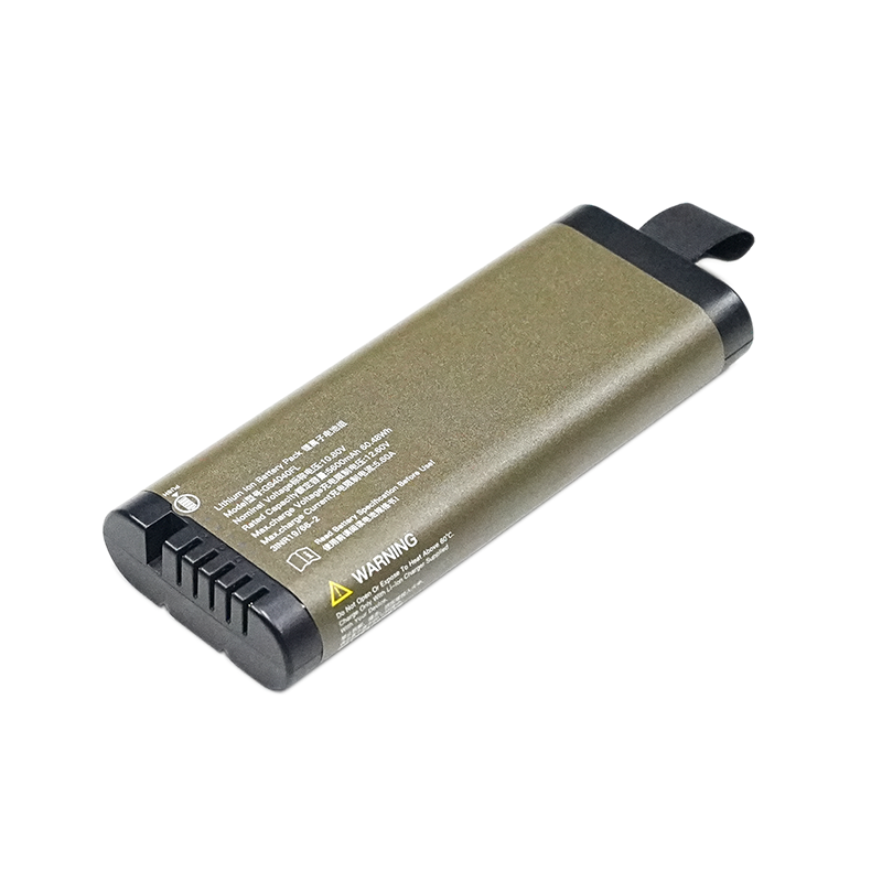
A 6-cell lithium battery pack configured in a 2S3P arrangement delivers a 7.4V (or 7.2V) nominal platform, whereas a 3S2P configuration yields an 11.1V (or 10.8V) platform with identical total energy storage. Selecting a 2S3P configuration using 2200mAh 18650 cells creates a 7.4V / 6600mAh assembly, while a 3S2P arrangement produces an 11.1V / 4400mAh assembly. Both 6-cell configurations yield an identical total work capacity of 48.84 Wh ($8.14 Wh \times 6 = 48.84 Wh$). Hardware designers select between 7.4V and 11.1V options based on internal DC-DC switching regulator efficiency curves and system current draw requirements.
Voltage Droop and Internal DC Resistance Impacts Under Continuous Load
DC internal resistance (DCIR) inside lithium-ion cells causes instantaneous terminal voltage droop under heavy discharge loads ($V_{terminal} = V_{ocv} – I \times DCIR$). In high-current medical equipment, such as portable suction pumps or motorized surgical tools, voltage droop can push cell voltage below system cutoff thresholds even when State of Charge (SOC) remains above 20%. Selecting low-DCIR medical-grade cells minimizes voltage droop, ensuring continuous power delivery during high-current operational pulses.
BMS Voltage Monitoring and SMBus Fuel Gauge Integration
Integrating a Smart Battery Management System (BMS) with real-time individual cell voltage sensing prevents cell voltage imbalance and shields multi-cell assemblies from overvoltage conditions. Specifying engineered custom medical battery solutions ensures that protective circuitry continuously monitors individual cell channels during operating shifts.
Active Cell Voltage Balancing Mechanisms in Multi-Cell Strings
Active and passive cell voltage balancing equalizes individual series cell voltages during constant-voltage (CV) charging to prevent premature pack capacity degradation. Over multiple charge-discharge cycles, slight impedance variations cause individual cell voltages in series strings to drift apart. Passive balancing bleeds current from higher-voltage cells through bypass resistors, while active balancing redistributes charge between cells to maintain uniform cell voltage across the entire string.
Precision Voltage Sensing and SMBus Fuel Gauge Accuracy
System Management Bus (SMBus 1.1) fuel gauge ICs measure individual li ion battery cell voltage with millivolt precision to calculate State of Charge (SOC) and State of Health (SOH). Integrating precision analog front-end (AFE) voltage sensing enables fuel gauges to map dynamic open-circuit voltage curves (OCV), providing clinical end-users with precise remaining runtime predictions on medical device displays.
International Safety Standards and Voltage Tolerance Mandates
Adhering to global regulatory standards requires integrating redundant hardware voltage protection circuits that prevent cell operation outside specified voltage envelopes. Maintaining strict voltage limits protects device hardware and satisfies global market compliance requirements.
IEC 62133-2 and ISO 13485 Overvoltage and Undervoltage Compliance
The IEC 62133 safety standard mandates rigorous overcharge and forced discharge testing to confirm battery protection circuits prevent thermal runaway when cell voltage exceeds maximum limits. Certification protocols subject battery assemblies to continuous charging voltages up to 1.1 times maximum rated limits at elevated temperatures. Manufacturing battery packs within ISO 13485 quality systems guarantees lot-to-lot voltage matching and component traceability for clinical applications.
Frequently Asked Questions (FAQ)
What is the standard nominal li ion battery cell voltage?
The standard nominal li ion battery cell voltage for standard NMC and LCO chemistries is 3.6V or 3.7V per cell. This nominal rating represents the average operating voltage during a complete discharge cycle at standard discharge rates.
What happens if a li ion battery cell voltage drops below 2.5V?
Discharging a li ion battery cell below 2.5V causes severe electrolyte decomposition, copper dissolution on current collectors, and permanent capacity loss. Operating below this threshold creates internal short-circuit risks during subsequent recharge attempts.
How does temperature affect li ion battery cell voltage under load?
Low ambient temperatures increase internal electrolyte viscosity and DC internal resistance, causing significant cell voltage droop under load. High temperatures temporarily decrease internal resistance but accelerate chemical degradation and permanent voltage loss over time.
What is the difference in cell voltage between 2S3P and 3S2P pack configurations?
A 2S3P configuration connects two series strings of three parallel cells for a nominal voltage of 7.4V (or 7.2V), whereas a 3S2P configuration connects three series strings of two parallel cells for a nominal voltage of 11.1V (or 10.8V). Both arrangements deliver identical total Watt-hour energy capacity when using identical cells.
Why is individual cell voltage monitoring required in medical battery packs?
Individual cell voltage monitoring ensures that no single series cell exceeds safe upper charge limits or drops below minimum discharge cutoffs. Real-time voltage sensing enables BMS balancing algorithms to maintain cell uniformity, preventing pack failure during critical medical procedures.