A service technician reverses the jumper clamps for two seconds; the 12 V bus sees −12 V. The alternator’s rectifier diodes short across the battery, a 120 A fusible link vaporizes, and the body control module never boots again. The same failure logic scales up: in a 48 V industrial lithium pack, a reversed polarity battery connection destroys the BMS front end, forces cells into reverse charging, and can trigger venting within minutes. Reverse polarity is not a user-error footnote — it is a design requirement, addressed through mechanical keying, protection electronics, and written specifications.
Key Takeaways
– Hooking a car battery up backwards sends reverse current through the alternator rectifier diodes and every unprotected ECU; damage typically starts with the alternator, main fuses, and fusible links within seconds.
– Positive and negative battery terminals follow physical coding — the SAE positive post measures 19.5 mm (0.77 in) versus 17.5 mm (0.69 in) for the negative post — and keyed connectors plus wrong polarity indicators eliminate most field errors.
– Lithium battery packs need electronic reverse-polarity protection (P-channel MOSFET or ideal-diode circuits) combined with BMS safeguards and UN 38.3 / IEC 62133-2 validation, specified in writing before first article.
What Happens If You Hook a Car Battery Up Backwards?
Which Vehicle Components Fail First in a Reverse Polarity Car Battery Event?
In a reverse polarity car battery event, the alternator rectifier diodes fail first — within seconds — followed by main fuses and fusible links, then unprotected ECUs.
- Alternator rectifier: the diode bridge conducts massively under reverse bias, shorting the battery through the stator and overheating within seconds.
- Main fuses and fusible links: 80–120 A class links blow as designed sacrificial elements, but a fuse is never faster than a semiconductor junction.
- ECUs, PCM, BCM, ABS modules: units without diode or MOSFET input protection suffer reversed supply rails and latch-up damage.
- Infotainment and aftermarket electronics: amplifiers and dash cameras with minimal input protection are frequent casualties.
- The battery itself: reverse connection forces reverse charging into the lead-acid battery, warping plates and shedding active material.
In summary, a reversed car battery creates a race between the fuse and the electronics — and the fuse usually loses.
What Happens If You Hook Up Jumper Cables Backwards?
Hooking up jumper cables backwards connects two 12 V batteries in opposition — a ~24 V differential across a near-zero-resistance loop — driving hundreds of amps through the clamps immediately.
- Immediate symptoms: a large spark at the final clamp, rapid cable heating, and possible melting of clamp insulation.
- Both batteries at risk: the discharged and the donor battery both see forced reverse current; lead-acid batteries under reverse charge generate hydrogen, which the connection spark can ignite.
- Electronics exposure: with clamps reversed, vehicle electronics see reverse voltage for the full connection duration.
- Correct jump-start sequence: red clamp to dead battery positive (+), red clamp to donor positive (+), black clamp to donor negative (−), black clamp to an unpainted engine-block ground on the dead vehicle — never to the dead battery’s negative terminal.
In summary, reversed jumper cables endanger both vehicles and both batteries; the correct four-clamp sequence removes most of the risk.
How Do You Identify Negative and Positive Battery Terminals?
What Physical Markings Distinguish Positive and Negative Battery Terminals?
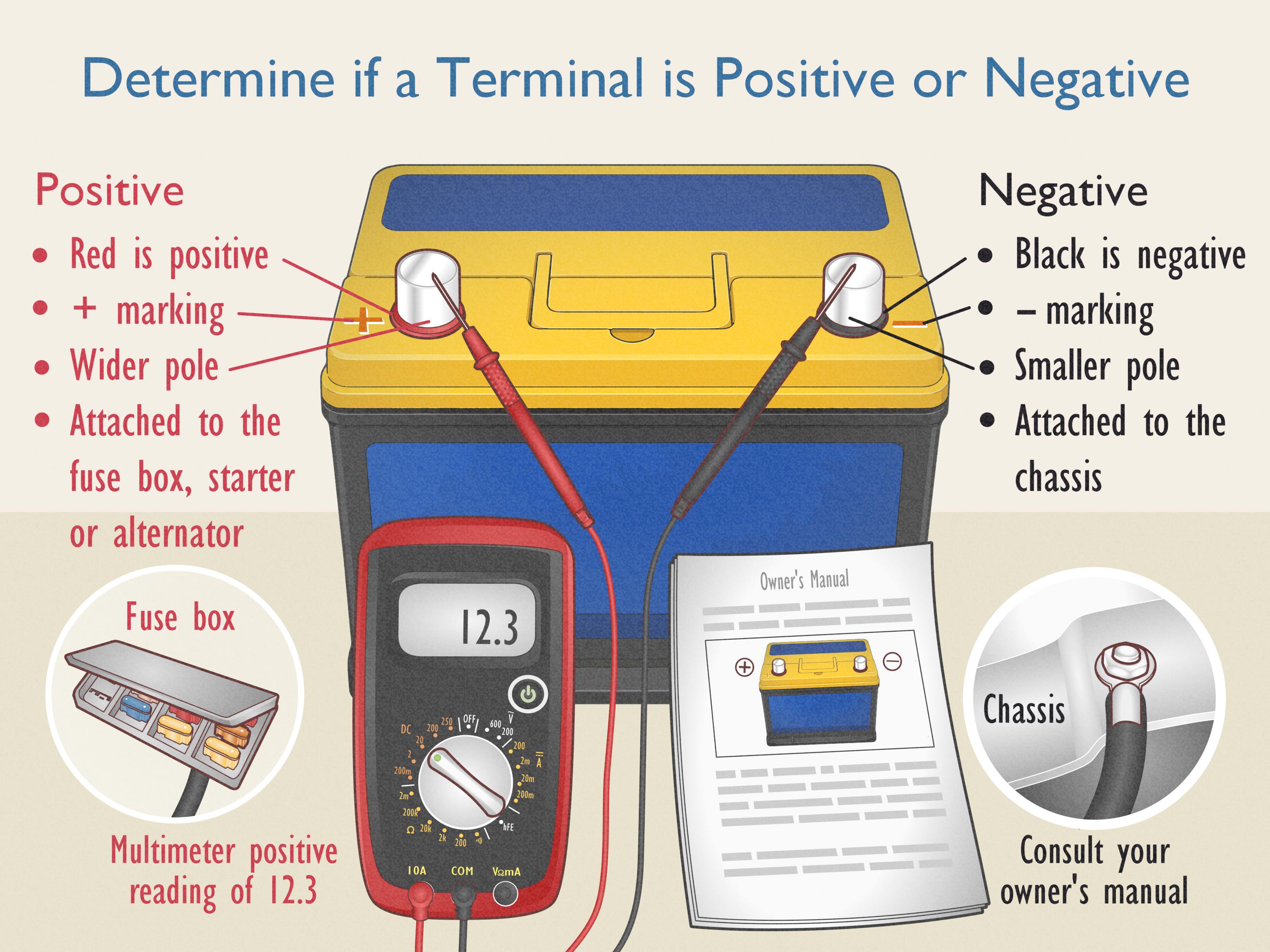
Battery polarity identification relies on four redundant layers: symbols (+/−), color coding (red/black), post sizing, and connector keying — verified with a multimeter whenever markings are unclear.
- Symbols and labels: the positive terminal carries a “+” and often a red cover; the negative terminal carries a “−” and black or no cover.
- Cable color: red cable to positive, black cable to negative (chassis ground) in 12 V automotive wiring.
- SAE tapered post sizing: per SAE convention, the positive post measures 19.5 mm (0.77 in) at the top, the negative post 17.5 mm (0.69 in) — so a negative clamp cannot seat fully on a positive post.
- Connector keying on packs: industrial lithium packs use asymmetric housings (XT60, XT90, or custom keyed connectors) that physically prevent reversed insertion.
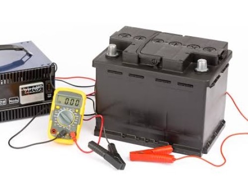
- Multimeter verification: a reading of +12.6 V with the red probe on the presumed positive terminal confirms polarity; a negative reading means the probes are reversed.
In summary, terminal identification is a designed redundancy system — demand all four layers on any custom pack.
What Is a Wrong Polarity Indicator and When Do You Need One?
A wrong polarity indicator is a passive or active warning device — LED, buzzer, or smart-clamp alarm — that alerts the operator before current flows.
- LED/buzzer indicators: simple circuits light a red LED and sound a buzzer when polarity is reversed; cost is negligible at pack level.
- Smart jump starters: modern lithium jump starters detect reversed clamps, block output, and alarm the operator.
- Charger-side indicators: industrial chargers display polarity fault codes and refuse to start a charge cycle on a reversed connection.
- When required: field-replaceable batteries, public-facing service (roadside assistance, rental fleets), or untrained end users all demand a wrong polarity indicator plus mechanical keying.
In summary, indicators warn, but only keying prevents.
How Does Reverse Polarity Damage Lithium Battery Packs and How Do Protection Circuits Prevent It?
Why Is a Reversed Polarity Battery Event More Dangerous in Lithium Packs?
A reversed polarity battery event in a lithium-ion or LiFePO4 pack is more dangerous than in lead-acid systems because lithium cells cannot tolerate reverse charging — forced reverse current drives lithium plating, rapid gas generation, and potentially thermal runaway.
- Cell-level damage: reverse charging a lithium-ion cell plates metallic lithium on the anode; even short events create permanent capacity loss and internal short risk.
- Series-string amplification: in a series pack, one reversed cell becomes a load driven backwards by the remaining cells, accelerating venting and rupture risk.
- BMS destruction: reversed pack voltage destroys the BMS front end and charge/discharge MOSFETs, removing every software safeguard when it is needed most.
- Charger-side hazards: a reversed charger can drive uncontrolled current into the pack, defeating CC-CV control entirely.
In summary, lithium chemistry offers no graceful degradation under reverse polarity — protection must act before current flows.
Which Reverse-Polarity Protection Circuit Fits Your Battery Pack?
Four mainstream protection architectures protect battery packs against reverse polarity; the P-channel MOSFET circuit offers the best balance of low loss and cost for most industrial packs, while keyed connectors provide the only truly passive prevention.
|
Protection Method |
Voltage / Power Loss |
Typical Current Range |
Cost Level |
Failure Coverage |
Best Fit |
|---|---|---|---|---|---|
|
Series Schottky diode |
0.3–0.5 V drop; notable heat above a few amps |
Low current (<5 A) |
Low |
Blocks reverse flow only |
Small electronics, low-drain devices |
|
P-channel MOSFET |
Milliohm-level Rds(on); minimal drop |
5–100 A class |
Medium |
Blocks reverse connection at input |
Industrial lithium packs, 12–48 V systems |
|
Ideal-diode controller + MOSFET |
Near-zero drop |
10–200+ A class |
Higher |
Blocks reverse flow plus ORing |
High-current packs, redundant supplies |
|
Keyed/anti-reverse connector (e.g., XT60, XT90) |
Zero |
Connector rating (30–90 A class) |
Low |
Prevents reversed mating entirely |
Field-swappable packs, OEM equipment |
The comparison shows that protection layers are complementary: keyed connectors prevent the error, MOSFET circuits limit damage when an error bypasses the mechanics, and fuses clear the residual fault. Automotive-grade designs additionally validate against ISO 16750-2 reverse-voltage requirements.
How Should B2B Buyers Specify Reverse-Polarity Protection in Custom Battery Packs?
How Do Protection Levels Compare on Cost and Risk Coverage?
Procurement teams should treat reverse-polarity protection as a specified deliverable, because each protection layer adds cents-to-dollars per pack while removing six-figure field-failure risks.
|
Protection Level |
Typical Content |
Cost Adder per Pack |
Residual Risk |
Best Fit |
|---|---|---|---|---|
|
Level 0 — Marking only |
Labels, red/black wires |
Negligible |
High — relies on operator |
Never recommended for B2B |
|
Level 1 — Keyed connector |
Anti-reverse housing, polarized pinout |
Low |
Wiring errors inside pack remain |
Field-swappable consumer/industrial packs |
|
Level 2 — Keyed + MOSFET protection |
Level 1 plus P-MOSFET or ideal-diode input stage |
Medium |
Internal miswiring during assembly |
Medical, robotics, security system packs |
|
Level 3 — Full protection + BMS interlock |
Level 2 plus BMS polarity sensing, charger handshake, wrong polarity indicator |
Higher |
Minimal |
Infrastructure, high-energy, mission-critical packs |
For OEM programs specifying custom battery packs with defined reverse-polarity protection — from connector selection through BMS integration and validation testing — request a custom battery pack consultation to match the protection level to the field-service environment.
What Should a Reverse-Polarity Procurement Specification Include?
A robust B2B specification converts reverse-polarity protection from a design intention into testable acceptance criteria.
- Mechanical keying: connector family, pinout drawing, and mating-cycle rating; prohibit non-keyed terminals on field-replaceable packs.
- Electrical protection: specified architecture (P-MOSFET, ideal diode, or BMS interlock), maximum reverse withstand voltage, and maximum leakage in the blocked state.
- Fault behavior: required response — alarm, output lockout, or fault code — plus a wrong polarity indicator for manual connections.
- Compliance evidence: UN 38.3 transport test summary, IEC 62133-2 or UL 2054 certification, and reverse-connection test records from first-article inspection.
- Automotive programs: ISO 16750-2 reverse-voltage and ISO 7637-2 transient immunity test results.
- Service documentation: terminal identification diagram and a verified replacement procedure in the service manual.
In conclusion, every reverse-polarity incident is preventable at the specification stage — contact the engineering team for a customized battery solution to define keyed connectors, protection electronics, and the validation plan for your application.