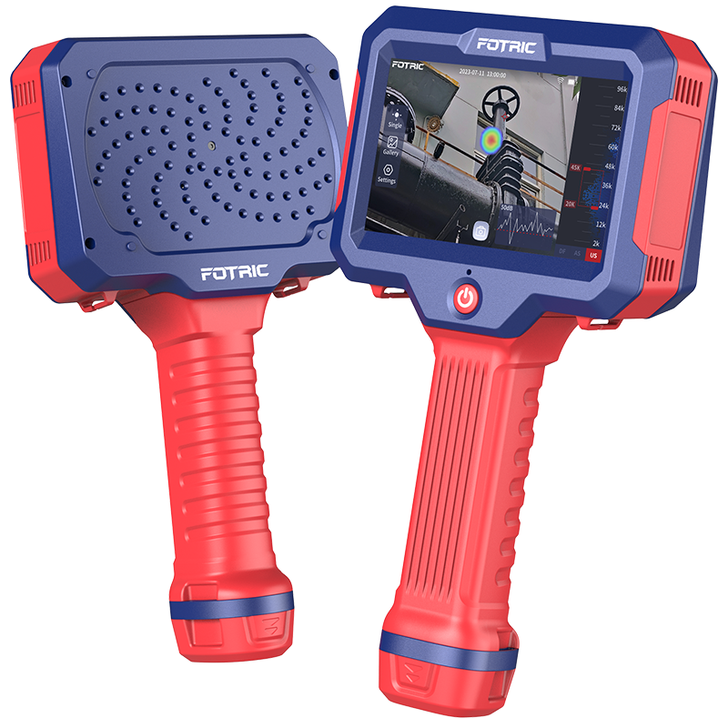
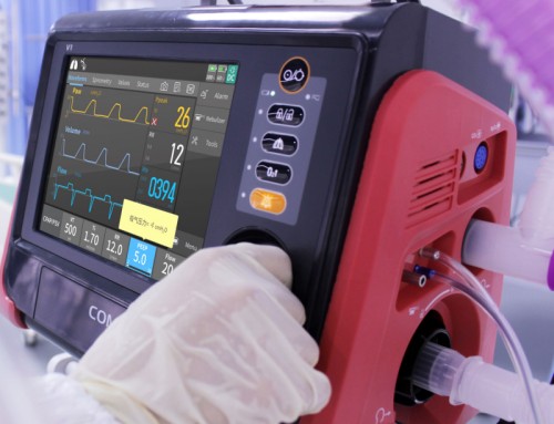
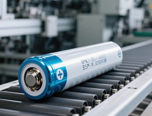
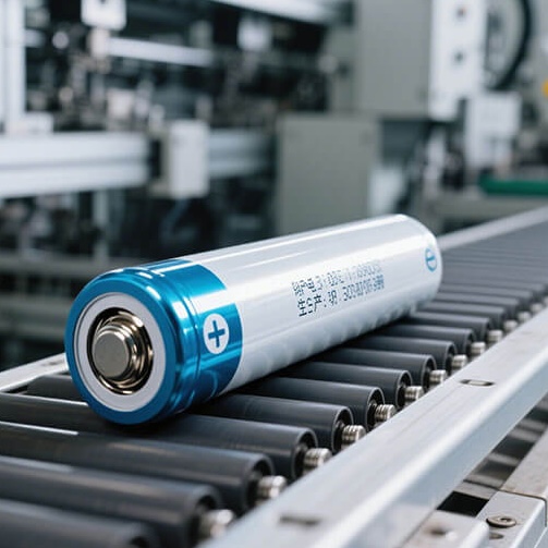
An optimal battery solution for infrared thermal imaging devices pairs high-density 18650 or 21700 lithium-ion cells with a low-noise, high-precision SMBus/I2C Smart BMS featuring active thermal decoupling, achieving cell internal resistance matching under 3mΩ, ±1% SOC accuracy, and IP67 sealing to eliminate sensor thermal distortion and ensure 8+ hours of continuous field operation.
Why Do Infrared Thermal Imagers Require Specialized Custom Battery Designs?
Infrared thermal imaging devices—ranging from handheld industrial inspection cameras and gas leak detectors to medical thermal scanners and firefighting vision tools—impose unique hardware constraints that off-the-shelf lithium-ion battery packs fail to satisfy. The central engineering challenge lies in the extreme sensitivity of the uncooled microbolometer sensor (VOx or a-Si). Microbolometers detect subtle temperature differential signals down to Noise Equivalent Temperature Differences (NETD) of less than 30mK. Because thermal detectors convert infrared radiation into pixel resistance variations, any localized parasite heat generated by internal electronics directly affects image calibration and creates spatial thermal noise.
Standard lithium-ion battery packs exhibit dynamic internal resistance (IR) variations during discharge. Under transient peak current loads—such as thermal shutter calibration solenoid cycles, laser rangefinder activation, or high-brightness LCD backlight bursts—high IR cells experience sudden voltage drops ($I \times R$ drop) and local Joule heating ($I^2R$ loss). When an unshielded battery pack heats up adjacent to the optical core, it induces a non-uniform thermal gradient across the detector housing. This gradient causes sensor gain drift, requiring frequent mechanical shutter re-calibrations and creating visual artifacts on the thermal image.
High-grade thermal imager battery architectures mandate strict cell sorting where DC internal resistance (DCIR) variation between series cells is held within $\Delta R_{\text{DC}} \le 3.0\text{ m}\Omega$ and cell capacity variance $\Delta Q \le 0.5\%$. Keeping cell IR mismatch below 3mΩ lowers battery pack operational self-heating by up to 35% under 2.5A discharge bursts, directly stabilizing microbolometer focal plane temperatures within $\pm 0.1^\circ\text{C}$.
Furthermore, field thermal cameras must endure rigorous operational conditions, including ambient temperatures from -20°C in utility line inspections to +60°C in furnace audits, alongside drop impacts and high moisture exposure. Fulfilling these demands requires a holistically optimized power architecture integrating low-noise cell chemistries, custom physical layout spacing, and precision SMBus smart battery management system (BMS) electronics.
Key Engineering Criteria for Thermal Imager Battery Pack Architecture
1. Precision Cell Selection and Internal Resistance Matching
Designing an industrial or medical-grade thermal camera battery begins with cell chemistry selection. While high-energy-density nickel-manganese-cobalt (NMC) 18650 or 21700 cylindrical cells remain the benchmark for handheld form factors, lithium polymer (LiPo) pouch cells offer custom dimensional freedom for ultra-thin ergonomic grips. To eliminate thermal hot spots, cells undergo rigorous 5-point grading prior to pack assembly. Voltage differential across series cells must not exceed 5mV at assembly, while internal resistance matching ensures equal current distribution across parallel branches, preventing localized thermal stress.
2. Low-Noise, Low-EMI Smart BMS Electronics
The Battery Management System serves as both safety controller and telemetry hub. Standard switching charge/discharge controllers often introduce high-frequency electromagnetic interference (EMI) ripple into the power rail, degrading sensitive microbolometer analog-to-digital converters (ADC). Specialized thermal imager BMS designs employ synchronous buck-boost topology with integrated LC filtering, maintaining voltage ripple below 15mV peak-to-peak under full load. Integrating Texas Instruments BQ40z50 or similar Impedance Track™ gas gauge ICs enables SMBus v1.1 or I2C communication, delivering precise State-of-Charge (SOC), State-of-Health (SOH), and remaining runtime reporting accurate to within ±1% across the entire temperature spectrum.
3. Physical Thermal Decoupling and Rugged Enclosure Sealing
To prevent battery thermal emissions from reaching the infrared sensor array, structural design relies on active thermal isolation. The battery chamber is isolated from the optical core using low-thermal-conductivity materials such as polycarbonate-ABS blends combined with aerobic thermal barrier foam or phase-change materials (PCM). Silicone thermal pads route excess heat away from the core toward external housing heat sinks. For outdoor and industrial field use, over-molded enclosure design achieves IP67 ingress protection and satisfies UN 38.3 vibration and mechanical shock criteria.
Technical Comparison Matrix: Custom Battery Archetypes for Thermal Imaging OEMs
| Engineering Parameter |
Compact Handheld Imager (2S1P 18650) |
Heavy-Duty Industrial Camera (3S2P 21700) |
Ultra-Slim Inspection Scanner (1S2P LiPo Pouch) |
| Nominal Voltage & Capacity |
7.2V / 3,400 mAh (24.48 Wh) |
10.8V / 10,000 mAh (108.0 Wh) |
3.7V / 6,000 mAh (22.20 Wh) |
| Max Continuous / Pulse Discharge |
5.0A Continuous / 8.0A Pulse (5s) |
15.0A Continuous / 25.0A Pulse (5s) |
4.0A Continuous / 6.0A Pulse (3s) |
| Cell Internal Resistance Variance |
$\Delta R_{\text{DC}} \le 3.0\text{ m}\Omega$ |
$\Delta R_{\text{DC}} \le 2.5\text{ m}\Omega$ |
$\Delta R_{\text{DC}} \le 4.0\text{ m}\Omega$ |
| Thermal Noise Footprint |
Ultra-Low (< 0.15°C/hr rise) |
Low (Isolated Chamber Required) |
Ultra-Low (< 0.10°C/hr rise) |
| BMS Communication Protocol |
SMBus v1.1 / HDQ |
SMBus v1.1 / CANbus 2.0B |
I2C / Gauge Telemetry |
| Operating Temp Range |
-20°C to +60°C (Charge: 0~45°C) |
-30°C to +65°C (Heater Optional) |
-10°C to +55°C |
| Ingress & Ruggedization |
IP67 Sealed / 1.5m Drop Tested |
IP67 Sealed / MIL-STD-810G Drop |
IP65 Enclosed / Compact Frame |
Solving Low-Temperature Voltage Sag and Fuel Gauge SOC Drift
Field inspectors frequently operate thermal imagers in freezing environments, such as electrical substation monitoring in winter or cold-storage facility audits. Under temperatures below 0°C, traditional lithium electrolytes suffer from reduced ionic conductivity and increased charge-transfer resistance, causing severe voltage drops when high-power peripherals start up. To counter this, custom low-temperature cell formulations utilize high-molarity lithium hexafluorophosphate ($\text{LiPF}_6$) salts combined with low-viscosity carbonate solvents. This chemical optimization maintains over 80% usable capacity at -20°C under a 0.5C discharge rate.
Another major engineering issue in thermal imaging power management is fuel gauge SOC drift caused by non-linear pulsed loads. Standard Coulomb-counting algorithms accumulate integration errors when exposed to fast pulse current spikes from laser rangefinders and shutter solenoids. Implementing dynamic internal resistance tracking via SMBus gas gauges continually recalibrates cell impedance models based on real-time temperature and load current. The system communicates remaining operating minutes directly to the imager’s main operating system, preventing abrupt power cut-offs during critical inspection sequences.
Regulatory Compliance and Quality Standards for Global OEM Export
Bringing a medical or industrial thermal imaging product to international markets requires full compliance with international safety and transport standards. Custom battery packs must undergo comprehensive testing protocols before mass production:
-
UN 38.3 Transport Testing: Mandatory for air and ground transport safety, encompassing altitude simulation, thermal cycling, vibration, shock, external short-circuit, impact, overcharge, and forced discharge evaluations.
-
IEC 62133-2 / UL 2054 Certification: Defines electrical and mechanical safety requirements for portable sealed secondary lithium cells and packs used in industrial and medical equipment, preventing thermal runaway and casing over-pressurization.
-
ISO 13485 Quality Management: For OEM thermal scanners intended for human fever screening or medical diagnostic applications, battery manufacturing lines must operate under strict ISO 13485 quality management systems, maintaining full component traceability from raw cell lot to finished pack serial number.
Frequently Asked Questions by Thermal Imager OEM Engineers
Q1: How does battery self-heating affect infrared sensor accuracy, and how can it be mitigated?
Battery self-heating creates thermal gradients across the camera body, causing microbolometer sensor calibration drift. It is mitigated by matching cell DC internal resistance ($\Delta R \le 3\text{m}\Omega$) to minimize Joule heating, employing low-ripple switching BMS controllers, and physically isolating the battery bay with low-thermal-conductivity materials.
Q2: Why is SMBus v1.1 or I2C communication essential for high-precision thermal imaging devices?
SMBus and I2C protocols allow the battery’s smart gas gauge IC to transmit real-time state-of-charge, voltage, current, temperature, and cell health metrics to the host processor. This enables dynamic power management, accurate runtime prediction, and safe shutdown sequences without sudden power loss.
Q3: What cell configuration provides the best balance of runtime and weight for handheld thermal cameras?
A 2S1P or 2S2P 18650/21700 cylindrical pack (7.2V nominal) provides the ideal voltage window for buck-boost converters, providing high energy density (>250 Wh/kg), robust structural integrity, and 6 to 10 hours of continuous field operation in a balanced handheld grip.
Q4: Can standard off-the-shelf 18650 battery packs be used in medical or industrial thermal scanners?
Off-the-shelf packs lack cell IR matching, low-noise BMS filtering, and low-temperature chemistry optimization. They often cause thermal sensor noise, fuel gauge inaccuracy, and failure to meet strict IEC 62133-2, UL 2054, or medical ISO 13485 compliance requirements.
Accelerate Your Thermal Imaging Power Architecture with Tefoo Energy
Developing a high-performance infrared thermal imaging device requires a power system that delivers stable voltage, zero thermal interference, and reliable cold-weather operation. Whether your project requires standard 18650/21700 modular configurations or a deep custom-engineered lithium polymer battery solution with SMBus integration and custom IP67 tooling, Tefoo Energy provides complete end-to-end engineering support.
Partner with our senior battery application engineers to accelerate your design cycle. Submit your project requirements to receive comprehensive technical design proposals, custom BMS protocol specifications, 3D STEP CAD models, and IEC/UL test documentation.