A single cold weld joint on a 96-cell series string adds milliohms of contact resistance, overheats at rated current, and fails vibration testing months after shipment. A single overpowered pulse drives heat through the cell cap, damages the separator, and creates a latent internal short. To weld battery cells correctly, engineers must control a narrow process window: enough energy to fuse the nickel strip to the terminal, but not enough to heat the cell. This guide defines that window, verification methods, and procurement criteria.
Key Takeaways
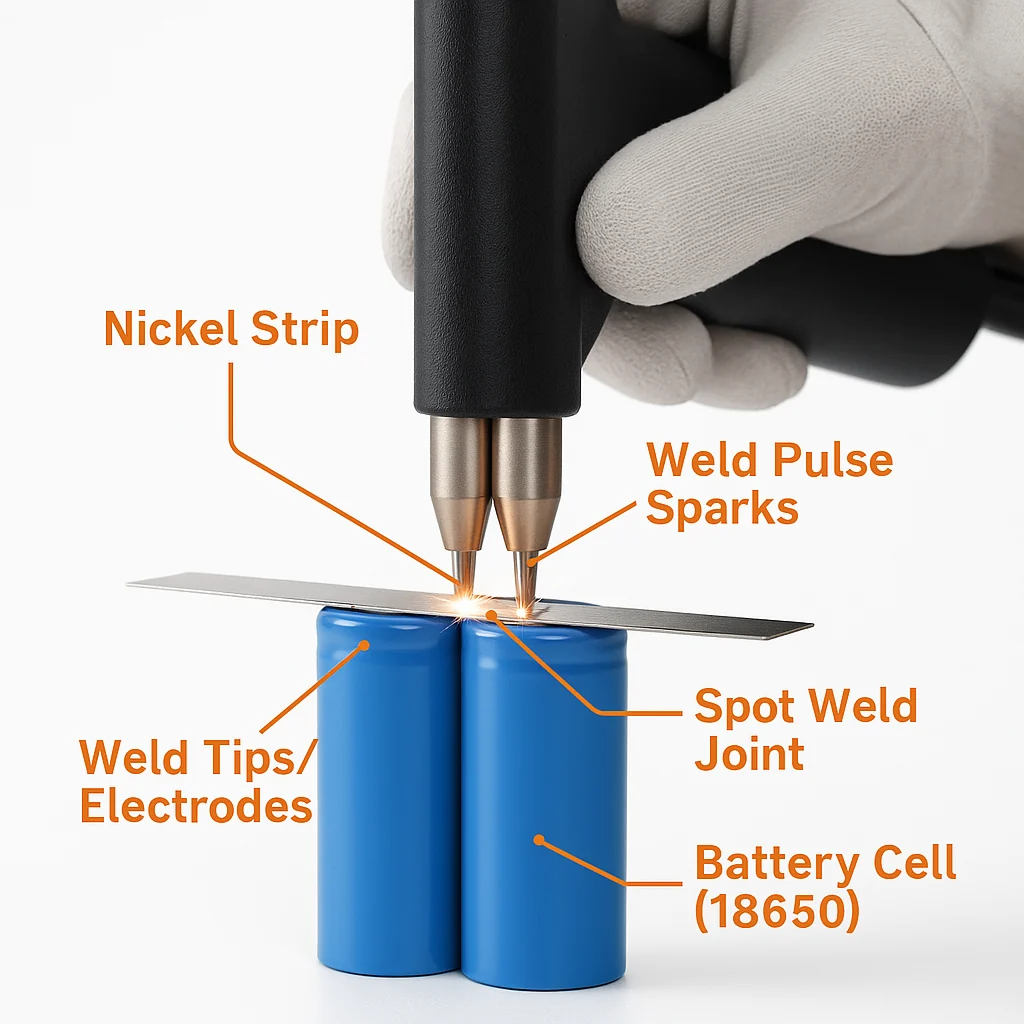
– Resistance spot welding is the industry-standard method to weld battery cells: millisecond current pulses fuse nickel strip to the terminal while internal cell temperature rise stays negligible.
– Nickel strip thickness must match the continuous pack current: typical designs use 0.1–0.3 mm (0.004–0.012 in) pure nickel, with copper or copper-nickel clad strip above ~30 A.
– Weld quality must be verified by peel/pull sampling, nugget inspection, and resistance measurement; B2B specifications should state pull force, sampling plans, and applicable standards (IEC 62133-2, UL 2054, UN 38.3) in writing.
What Is the Best Way to Weld Battery Cells Together?
Why Is Resistance Spot Welding the Standard Method to Weld Battery Terminals?
Resistance spot welding is the standard method to weld battery terminals because the process concentrates heat in a 2–4 mm (0.08–0.16 in) nugget for 2–20 milliseconds, while cell internals stay near ambient temperature.
- Localized heat input: the pulse is far shorter than the thermal time constant of the cell can, so heat never reaches the jellyroll or separator.
- Low joint resistance: a properly formed nugget adds only a fraction of a milliohm per joint, preserving pack efficiency at high discharge rates.
- No consumables: unlike soldering, spot welding adds no filler metal, flux residue, or thermal soak to the cell top.
- Automation-ready: servo weld heads with current and force feedback integrate directly into high-volume lines.
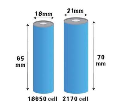
In summary, resistance spot welding is the only mainstream process combining millisecond thermal confinement with production throughput on cylindrical 18650/21700 cells.
How Do the Main Methods to Weld Battery Tabs Compare?
Resistance spot, laser, and ultrasonic welding each weld battery interconnects reliably, but each fits a different conductor material, tab thickness, and volume; manual soldering is not recommended for direct cell-top joints.
|
Welding Method |
Heat Into Cell |
Typical Joint Resistance |
Compatible Conductors |
Throughput |
Typical Application |
|---|---|---|---|---|---|
|
Resistance spot |
Very low (ms pulse) |
<0.5 mΩ |
Pure nickel, Ni-plated steel, thin Cu |
0.5–2 s/weld |
18650/21700 pack interconnects |
|
Laser welding |
Low (focused beam) |
<0.2 mΩ |
Cu, Al, Ni, mixed metals |
1–5 s/weld |
Prismatic/pouch busbars, EV packs |
|
Ultrasonic welding |
Very low (no melting) |
<0.2 mΩ |
Al tabs, Cu foils, multi-layer stacks |
1–3 s/weld |
Pouch tab stacks, Al joining |
|
Manual soldering |
High (seconds of soak) |
1–5 mΩ |
Ni, Cu |
Slow |
Prototypes only — avoid on cell tops |
The comparison shows that the optimal process depends on conductor material first and volume second: nickel strip on cylindrical cells belongs to spot welding, aluminum pouch tabs to ultrasonic welding, and copper prismatic busbars to laser welding.
What Welding Parameters Produce Reliable Battery Interconnects?
How Should Nickel Strip Material and Thickness Match Pack Current?
Strip sizing is the first design decision when engineers weld battery interconnects: an industry rule of thumb assigns roughly 5–7 A continuous per 10 mm (0.39 in) of width for 0.15 mm (0.006 in) pure nickel.
- 0.1 mm (0.004 in) pure nickel: low-current packs, up to ~5 A per 10 mm width; easy to weld with capacitor-discharge welders.
- 0.15 mm (0.006 in) pure nickel: the mainstream choice; typical continuous ~5–7 A per 10 mm width.
- 0.2 mm (0.008 in) pure nickel: mid-current packs; requires higher weld energy or dual-pulse profiles.
- 0.3 mm (0.012 in) pure nickel: ~15 A class per 10 mm width; verify welder peak current first.
- Copper or copper-nickel clad strip: for continuous currents above ~30 A; copper offers roughly 4× the conductivity of nickel but demands higher peak current or laser welding.
- Avoid nickel-plated steel in high-current paths: the steel core has roughly one-third the conductivity of pure nickel and inflates I²R heating.
In summary, engineers should size strip cross-section from the current budget, then confirm the welder can qualify a nugget on that exact strip-cell pairing.
Which Process Window Settings Control Heat When You Weld Battery Cells?
A controlled process window — weld energy, pulse profile, electrode force, and electrode condition — decides whether the nugget forms or the cell absorbs damaging heat.
- Pulse duration: typical 2–20 ms for 0.1–0.2 mm nickel on cylindrical terminals; dual-pulse profiles (cleaning pulse plus main pulse) improve consistency on plated surfaces.
- Peak current/energy: capacitor-discharge settings for 0.15 mm nickel on 18650 cans typically fall in the few-hundred-joule range; qualify on sacrificial cells, because can plating varies by manufacturer.
- Electrode force: typical 10–40 N per electrode; insufficient force causes expulsion and spatter, while excessive force thins the nugget.
- Electrode maintenance: dress or replace electrodes at defined weld-count intervals, because electrode mushrooming spreads current density and weakens welds.
- Cell-side protection: weld on the top cap or bottom can only, never the wrapper sidewall, and keep welds clear of CID and vent features per the cell drawing.
In summary, a qualified weld window is cell-specific: strip and welder settings do not transfer across cell models without requalification.
How Do You Verify Weld Quality on a Battery Pack?
Which Destructive and Non-Destructive Tests Qualify Battery Welds?
Battery weld qualification combines destructive peel/pull testing on samples with non-destructive visual and resistance checks on production units; no single test detects both weak fusion and heat damage.
- Peel test (destructive): a passing weld leaves a torn nugget button or pulled material in the strip, while a failing weld separates cleanly at the interface.
- Pull force test (destructive): measure peak separation force per nugget and record the distribution across samples, not just the mean.
- Visual inspection: check nugget diameter, indentation symmetry, discoloration, and expulsion marks under magnification.
- Joint resistance measurement: micro-ohmmeter or 4-wire Kelvin checks on representative joints flag cold welds before pack closure.
- Post-weld cell screening: monitor open-circuit voltage over 24–72 hours to catch weld-induced internal shorts before module assembly.
In summary, a production-ready weld process defines acceptance criteria for mechanical, visual, and electrical evidence, sampled per lot.
Which Standards and Documentation Should Welded Battery Packs Meet?
Welded battery packs for commercial sale must satisfy pack-level safety and transport standards, and the weld process must be documented as a controlled special process.
- IEC 62133-2: safety requirements for portable lithium cells and batteries, including mechanical and electrical stress tests on assembled packs.
- UL 2054: safety standard for household and commercial packs, covering construction and abnormal-operation tests.
- UN 38.3: transport testing (vibration, shock, thermal, short circuit) before shipment; vibration and shock results directly reflect weld integrity.
- Process documentation: weld parameter records, electrode maintenance logs, and first-article peel-test reports retained per lot.
In summary, standards compliance is evidence that weld quality survived vibration, shock, and abuse testing — request the UN 38.3 test summary and first-article weld data with every new pack design.
How Should B2B Buyers Source Welded Battery Pack Assembly?
How Do Manual, Semi-Automatic, and Automated Weld Lines Compare on TCO?
The correct weld production method depends on annual volume and quality-risk tolerance: manual bench welders suit prototypes, while automated lines with closed-loop monitoring deliver the lowest cost per qualified weld at high volume.
|
Production Method |
Typical Throughput |
Operator Skill |
Quality Monitoring |
Relative Cost per Weld |
Best Fit |
|---|---|---|---|---|---|
|
Manual bench welder |
200–1,000 welds/day |
High |
Visual only |
High |
Prototypes, repairs, low-volume packs |
|
Semi-automatic XY table |
2,000–8,000 welds/day |
Medium |
Current/force readout |
Medium |
Pilot runs, mid-volume packs |
|
Fully automated line |
10,000+ welds/day |
Low |
Closed-loop current, force, and displacement per weld; SPC logging |
Low |
EV, ESS, high-volume OEM programs |
The table shows that automation is a quality investment before a labor investment: closed-loop monitoring catches weak welds in-line, which manual inspection cannot do. For OEM programs that need custom battery packs with qualified, documented weld processes — from strip layout through UN 38.3 testing — request a custom battery pack consultation to scope volume, conductor material, and validation requirements early.
What Should a Welded-Pack Procurement Specification Include?
A robust B2B specification for welded battery packs defines the conductor stack-up, weld acceptance criteria, and traceability records in writing before first article.
- Conductor definition: strip material (pure nickel, copper, or clad), thickness in mm/in, width, and plating state, with a current-capacity calculation attached.
- Weld acceptance criteria: nugget count and pattern per cell, minimum pull/peel force with failure-mode definition, maximum joint resistance, and visual defect limits.
- Sampling plan: destructive test frequency per lot, plus reaction rules when a sample fails.
- Traceability: weld parameter logs, electrode change records, and machine ID linked to each pack serial number.
- Compliance evidence: IEC 62133-2 or UL 2054 certification, UN 38.3 test summary, and a first-article inspection report with peel photos.
In conclusion, sourcing welded packs against written acceptance criteria converts weld quality from an assembly-floor variable into a contractual deliverable — contact the engineering team for a customized battery solution to define the weld specification, validation plan, and certification path for your application.