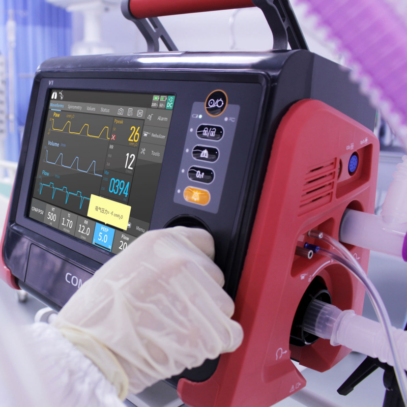
A portable ultrasound technician navigates a busy hospital ward, performing consecutive bedside diagnostic scans without returning the unit to its charging dock. Midway through a vascular assessment, the device triggers an unexpected low-battery warning, forcing a premature shutdown because the system’s battery sizing model failed to account for transient pulse loads during high-frequency Doppler imaging. Sizing power supplies for portable diagnostic devices demands more than dividing total energy by idle power consumption. Hardware engineers must rigorously model steady-state power draw, peak burst demands, DC-DC conversion inefficiencies, and thermal derating factors to determine the exact series-parallel ($S/P$) cell matrix required for reliable clinical operation.
Mathematical Formulas for Baseline Energy and Runtime Modeling
Calculating the required capacity for a medical diagnostic battery pack begins by establishing the device’s operational profile across different usage modes. Simply relying on average power draw yields inaccurate runtime estimates during active diagnostic procedures.
Defining Operational Duty Cycles and Average Power Consumption
Diagnostic equipment operates under cyclic load profiles, transitioning between low-power standby modes and high-power active sampling or scanning states. To determine true average power ($P_{\text{avg}}$), engineers must calculate a time-weighted sum across all operating modes:
$$P_{\text{avg}} = \frac{P_{\text{peak}} \cdot t_{\text{peak}} + P_{\text{standby}} \cdot t_{\text{standby}}}{t_{\text{total}}}$$
Where $P_{\text{peak}}$ represents active power draw during diagnostic cycles, $t_{\text{peak}}$ is the cumulative active run time, $P_{\text{standby}}$ is idle power consumption, and $t_{\text{total}}$ is the required total battery operation window.
Accounting for System Inefficiency and End-of-Life Derating
Raw energy calculation ($E = P_{\text{avg}} \cdot t$) must be adjusted for physical conversion losses and cell capacity degradation over time. Internal DC-DC converters typically operate at an efficiency ($\eta_{\text{conv}}$) between $85\%$ and $92\%$. Furthermore, medical standards mandate that battery packs maintain full operational runtime at their end-of-life (EOL) threshold—typically defined as $80\%$ remaining capacity ($\eta_{\text{aging}} = 0.80$).
The total required nominal energy ($E_{\text{required}}$) in Watt-hours ($\text{Wh}$) is calculated as:
$$E_{\text{required}} = \frac{P_{\text{avg}} \cdot t_{\text{run}}}{\eta_{\text{conv}} \cdot \eta_{\text{aging}}}$$
Translating Watt-Hour Requirements into 18650 Series-Parallel Configurations
Once total required energy ($E_{\text{required}}$) is established, the next step is selecting the appropriate series ($S$) and parallel ($P$) 18650 cell arrangement to match host system electrical requirements.
Determining Series Cell Count ($S$) for Voltage Matching
The series cell count determines the nominal operating voltage of the battery stack. Connecting cylindrical 18650 lithium-ion cells in series increases overall voltage while keeping capacity constant:
$$S = \frac{V_{\text{system\_nominal}}}{V_{\text{cell\_nominal}}}$$
For instance, pairing a $10.8\text{V}$ nominal medical system with standard $3.6\text{V}$ 18650 cells yields a $3\text{S}$ series configuration.
Calculating Parallel Cell Count ($P$) and Capacity Parameters
The parallel cell count determines total pack capacity in Ampere-hours ($\text{Ah}$) and maximum current delivery capability:
$$P = \left\lceil \frac{E_{\text{required}}}{S \cdot E_{\text{cell}}} \right\rceil$$
Where $E_{\text{cell}}$ is the stored energy per individual cell ($V_{\text{cell\_nominal}} \cdot C_{\text{cell\_rated}}$). For handheld X-ray scanners, portable imaging instruments, and diagnostic tools, a standardized 3S1P architecture utilizing high-energy-density Panasonic 18650 cells provides an optimal balance between capacity, weight, and mechanical enclosure limits.
| Engineering Parameter | Technical Specification (3S1P Standard Pack) | System Integration Impact |
| Series-Parallel Topology |
3S1P (Panasonic 18650 Cells)
|
Compact, lightweight power architecture for handheld tools
|
| Nominal Voltage / Energy |
10.8V / 35.64Wh
|
Direct alignment with medical DC-DC converter input stages
|
| Rated Capacity (Nominal) |
3300mAh (3450mAh)
|
High energy density supporting extended clinical diagnostic sessions
|
| Max Charge Voltage / Current |
12.6V / 2.41A
|
Controlled JEITA-based charge management parameters
|
| Max Discharge Current |
4.0A
|
Sustains high-power diagnostic imaging pulses without trip out
|
| Pack Internal Resistance |
<150mΩ @ 1kHz at 25°C
|
Minimizes voltage sag and $I^2R$ resistive heating under load
|
| Dimensions & Weight |
84.6mm × 58.5mm × 22.0mm | 180g ± 10g
|
Ergonomic, low-mass integration into handheld handles
|
| Compliance Matrix |
CE / FCC / IEC 62133 / UN38.3 / PSE / UKCA
|
Pre-certified platform streamlining global medical device registration
|
Factoring In Transient Pulse Loads and Voltage Sag Limits
In medical diagnostic devices—such as portable X-ray emitters or ultrasound Doppler transmitters—current demand is not constant. Pulsed loads induce immediate voltage drop across the battery’s internal impedance.
Calculating Internal Resistance ($R_{\text{DC}}$) and Terminal Voltage Drops
When a high-current diagnostic pulse ($I_{\text{pulse}}$) engages, terminal voltage ($V_{\text{terminal}}$) drops instantly below the open-circuit voltage ($V_{\text{ocv}}$) according to Ohm’s Law:
$$V_{\text{sag}} = I_{\text{pulse}} \cdot R_{\text{pack\_IR}}$$
$$V_{\text{terminal}} = V_{\text{ocv}} – V_{\text{sag}}$$
If a 3S1P battery pack exhibits an internal resistance of $<150\text{ m}\Omega$, drawing a peak discharge current of $4.0\text{A}$ creates a voltage sag ($V_{\text{sag}}$) of approximately $0.60\text{V}$.
Aligning Cutoff Thresholds to Prevent Unexpected Resets
If $V_{\text{terminal}}$ falls below the host instrument’s minimum operating voltage threshold ($V_{\text{system\_cutoff}}$), the internal power management IC will trip a low-voltage brownout reset, even if remaining state-of-charge reads $30\%$. Engineers must verify that:
$$V_{\text{cell\_min\_ocv}} – \left( \frac{I_{\text{pulse}} \cdot R_{\text{pack\_IR}}}{S} \right) > V_{\text{cutoff\_per\_cell}}$$
Selecting cells with low internal resistance and maintaining low-loss PCB routing keeps total pack resistance within strict boundaries, preventing false low-battery shutoffs during pulse bursts.
Smart BMS Communications and Thermal Temperature Derating
Battery capacity is highly sensitive to ambient operating temperatures. Sizing calculations must account for thermal boundaries enforced by intelligent Battery Management Systems (BMS).
Thermal Temperature Derating and JEITA Guidelines
At low temperatures ($<0^\circ\text{C}$), electrolyte viscosity increases, elevating internal impedance and reducing usable output capacity. Conversely, elevated operating temperatures accelerate chemical degradation. Standard medical battery platforms incorporate JEITA-based temperature-aware charge control, dynamically lowering maximum charge voltage and current limits to preserve cell health. Operating within certified charge ($0^\circ\text{C to }50^\circ\text{C}$) and discharge ($-20^\circ\text{C to }60^\circ\text{C}$) temperature windows ensures predictable capacity availability.
Telemetry Integration via SMBus v1.1 Protocols
Smart battery packs integrate high-precision fuel gauge ICs that communicate telemetry directly to the host equipment over SMBus v1.1 protocols. The fuel gauge continuously updates the
RemainingCapacity() (0x0F) and FullChargeCapacity() (0x10) registers, automatically adjusting runtime predictions based on real-time cell impedance, temperature, and cycle age. This guarantees that clinical users receive accurate percentage indicators throughout the battery’s 500-cycle lifespan (maintaining $\ge 80\%$ rated capacity).
For engineering teams developing portable diagnostic instruments and medical imaging devices, choosing field-tested, pre-certified power architectures drastically simplifies hardware integration and regulatory approvals. Explore technical specifications and documentation for our pre-certified standard battery packs to streamline your product development timeline.
Frequently Asked Questions (FAQ)
1. How do I calculate total Watt-hours needed for a handheld diagnostic tool?
Calculate Watt-hours by multiplying total average power consumption ($P_{\text{avg}}$ in Watts) by required operating time ($t_{\text{run}}$ in hours), then dividing by DC-DC conversion efficiency ($\eta_{\text{conv}}$) and end-of-life aging derating ($\eta_{\text{aging}}$, typically $0.80$).
2. Why is voltage sag critical when calculating 18650 pack capacity for X-ray or ultrasound tools?
Diagnostic tools generate high-current pulses during imaging passes. Voltage sag ($V_{\text{sag}} = I_{\text{pulse}} \cdot R_{\text{pack\_IR}}$) temporarily lowers terminal voltage. If terminal voltage drops below the host system’s minimum input threshold, the device resets abruptly regardless of calculated remaining capacity.
3. How does cycle-life degradation affect battery capacity calculations in medical devices?
As 18650 cells undergo charge-discharge cycling, chemical degradation reduces maximum usable capacity. Medical battery sizing models must use end-of-life capacity (typically $80\%$ of rated capacity after 500 cycles) as the baseline to ensure full operational runtime throughout the product’s service life.
4. What is the advantage of using a 3S1P 18650 configuration for portable medical instruments?
A 3S1P configuration delivers a nominal 10.8V platform with 35.64Wh of energy in a compact 180g footprint. This provides optimal voltage for medical DC-DC converters without adding bulk or operator fatigue in handheld tools.
5. Why should medical battery capacity calculations include SMBus fuel gauge data?
SMBus v1.1 fuel gauges track real-time changes in cell impedance, temperature, and aging. Transmitting these dynamic register values to the host device ensures that capacity calculations adjust automatically to environmental and operational conditions.