How Long to Charge a 3.7 V 18650 Battery in Medical Equipment Designs?
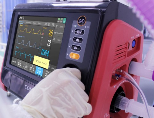
Clinical turnaround times for portable medical electrical equipment—such as mobile patient monitors, handheld diagnostic ultrasound scanners, infusion pumps, and portable oxygen concentrators—depend directly on predictable battery recharge cycles. When designing power systems for hospital equipment, medical device R&D engineers and procurement managers must accurately calculate how long to charge 3.7 v battery packs to prevent clinical workflow disruptions and avoid heat-induced component degradation. Determining the precise 3.7 v battery charging time involves analyzing cell milliamp-hour ($\text{mAh}$) capacity, charging current ($\text{mA}$ or $\text{A}$), Constant Current / Constant Voltage ($\text{CC/CV}$) profile transitions, and internal resistance compensation factors enforced by the Smart Battery Management System ($\text{BMS}$).
What Is the Mathematical Formula to Calculate 3.7 V Battery Charging Time?
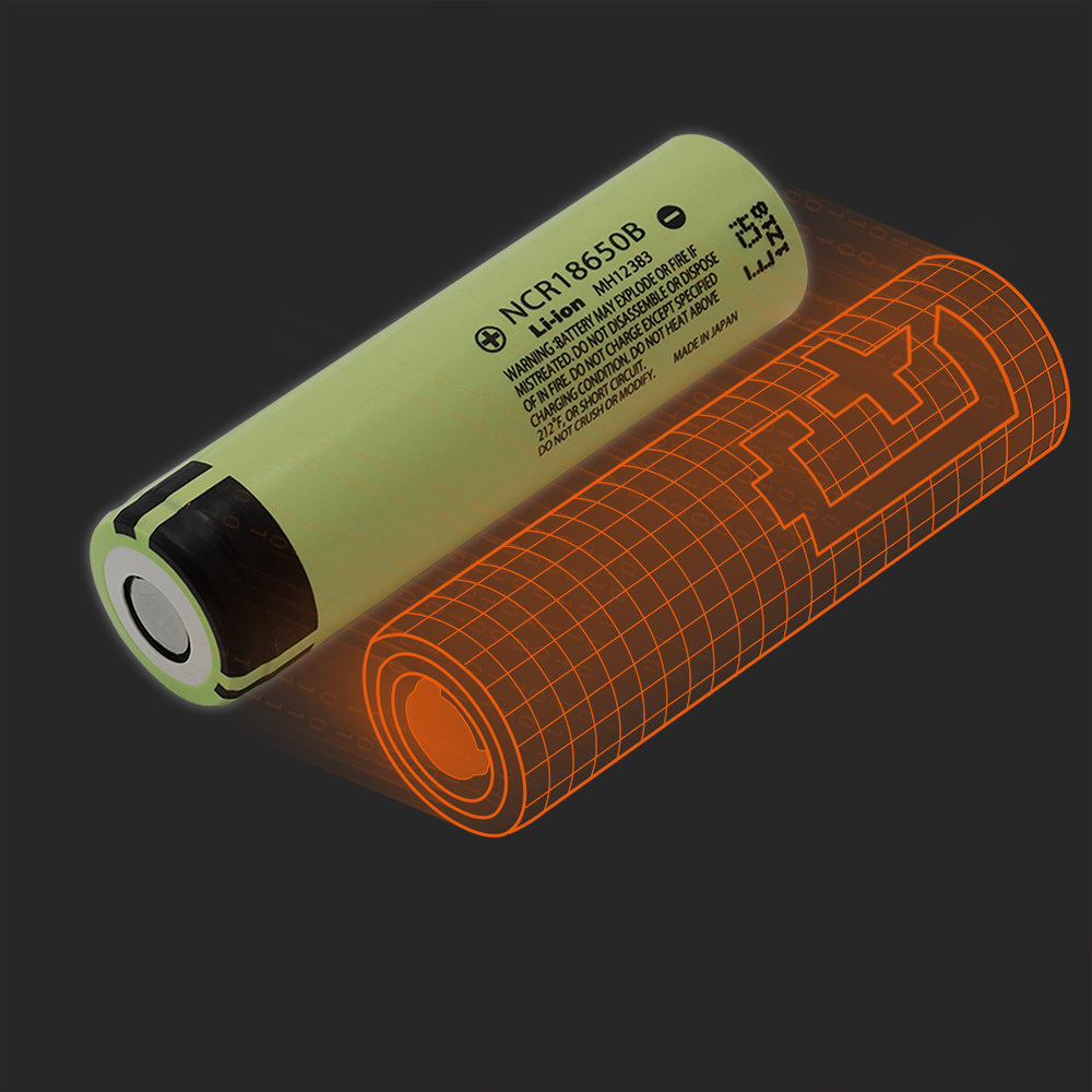
Calculating the 3.7 V battery charging time for an 18650 cell requires dividing the rated milliamp-hour capacity by the charge current and multiplying by an internal resistance efficiency factor ($1.2\text{–}1.5$) to account for energy losses during Constant Current / Constant Voltage (CC/CV) phases.
CC/CV Charging Phases and Resistance Factor Multiplication
The standard formula for 18650 battery charge time accounts for internal electrochemical resistance by applying a $1.2\text{ to }1.5$ multiplier to the basic capacity-to-current ratio. Because lithium-ion cells experience internal resistance ($R_{\text{DC}}$) during charging, energy is lost as heat, meaning the input charge efficiency is not $100\%$. The mathematical formula for 18650 battery charge time is expressed as:
$$\text{Charge Time (Hours)} = \left( \frac{\text{Rated Capacity (mAh)}}{\text{Charge Current (mA)}} \right) \times \text{Efficiency Factor}$$
National standards mandate charging under a current not exceeding $0.2\text{C}$ for standard baseline evaluations, where the baseline resistance factor is set to $1.2$. However, due to varying 18650 cell capacities ($1800\text{mAh to }3500\text{mAh}$) and charger topology differences across manufacturers, practical industrial calculation factors range between $1.2$, $1.3$, and $1.5$. Selecting a smaller factor models a highly efficient charger, resulting in a shorter calculated charge time.
How Does Charging C-Rate Impact 18650 Battery Charge Time and Cell Longevity?
Standard 0.2C charging charges a 3.7 V 18650 battery in 7.5 to 8.5 hours with minimal internal heating, whereas fast 0.5C to 1.0C charging reduces charge time to 1.5 to 3 hours at the expense of higher thermal stress.
Standard 0.2C Charging vs. Fast 0.5C–1.0C Charging Rates
Charging 3.7 V lithium-ion cells at a conservative 0.2C rate satisfies national standard safety baselines while maximizing total cycle lifespan. The C-rate expresses the charging current relative to the battery’s nominal capacity ($1\text{C}$ current for a $2600\text{mAh}$ cell equals $2600\text{mA}$). While fast charging at $0.5\text{C}$ or $1.0\text{C}$ significantly reduces how long to charge 18650 battery packs, higher currents generate internal Joule heating ($P = I^2R_{\text{DC}}$).
Applying high charging currents influences cell longevity and mechanical design in sealed medical electrical equipment:
-
Low Thermal Impact ($0.2\text{C}$ Charge Rate): Generates minimal heat, keeping cell temperatures near ambient and eliminating the need for active cooling fans in IP67-sealed medical monitors.
-
Moderate Thermal Impact ($0.5\text{C}$ Charge Rate): Cuts charging time to approximately $2.5\text{ hours}$, requiring thermal dissipation pads between the cell casing and outer chassis.
-
High Thermal Impact ($1.0\text{C}$ Fast Charge Rate): Reduces charge time to under $1.5\text{ hours}$, but risks lithium plating on the anode if charged at sub-ambient temperatures ($< 10^\circ\text{C}$).
How Does Smart BMS Firmware Control 3.7 V Lithium Battery Charging Cycles?
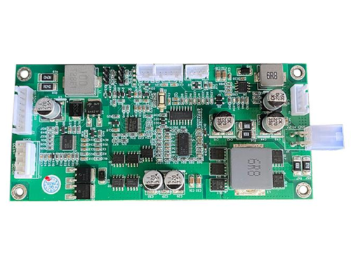
Smart Battery Management Systems (BMS) govern 3.7 V battery charging cycles by enforcing Constant Current / Constant Voltage (CC/CV) algorithms and cutting off current when cell voltage reaches 4.2V.
Overcharge Protection and Temperature Cut-off Limits under IEC 62133-2
Integrating a Protection Circuit Module (PCM) prevents overcharging damage by disconnecting charger input as soon as full charge termination thresholds are met. During the initial Constant Current (CC) phase, the charger feeds a steady current into the 3.7 V 18650 cell until its voltage climbs to $4.2\text{V}$. The BMS then switches to the Constant Voltage (CV) phase, holding the voltage at $4.2\text{V}$ while current gradually tapers down to a pre-set termination threshold (typically $0.02\text{C}$ to $0.05\text{C}$).
Under medical safety standard IEC 62133-2, certified by accredited bodies under the IECEE CB Scheme, the PCM protection IC must continuously monitor individual cell parameters. Continuing to supply current after full charge saturation risks electrolyte decomposition and casing over-pressurization. Stopping the charging process immediately upon indicator color change or automatic PCM cut-off preserves cell health and protects internal charger circuitry.
For medical equipment design teams choosing between cylindrical cell form factors, comparing physical footprints is another essential step—review our engineering analysis on [18650 vs 21700 for portable medical devices] to evaluate volumetric energy and thermal envelope differences.
What Design Strategies Reduce 18650 Battery Charge Time in Medical Workstations?
Optimizing charger thermal dissipation and selecting low-internal-resistance 18650 cells minimizes 3.7 V battery charge time without exceeding medical device surface temperature limits.
Thermal Isolation and Balanced Cell-String Charging Topologies
Active thermal isolation between the battery chamber and clinical electronic components maintains low cell temperature during high-current charging cycles. When designing multi-cell 18650 packs (such as 4S2P or 7S2P configurations for $14.4\text{V}$ or $24\text{V}$ medical devices), charging speed depends on individual cell balancing. Mismatched internal resistance across series cells forces the BMS to prolong the CV balancing phase, significantly extending overall pack charge time.
Key engineering strategies to optimize 18650 charge time include:
-
Automated Cell Grading: Sorting cells to match internal resistance ($\Delta R_{\text{DC}} \le 3\text{m}\Omega$) and capacity ($\Delta Q \le 0.5\%$) reduces BMS cell balancing time by up to 40%.
-
Synchronous Switching Buck Chargers: Utilizing high-efficiency switching charger ICs ($>92\%$ efficiency) reduces waste heat compared to linear regulators during the CC phase.
-
Multi-NTC Thermistor Monitoring: Placing NTC thermistors directly against center cells in the 18650 matrix ensures fast charge rates automatically throttle back if internal pack temperatures exceed $45^\circ\text{C}$.
Frequently Asked Questions
Q1: How long does it take to charge a 3.7 V 2600mAh 18650 battery?
A 3.7 V 2600mAh 18650 battery takes approximately 7.8 hours to charge at a standard 500mA current.
-
Calculation: $(2600\text{ mAh} \div 500\text{ mA}) \times 1.5 \text{ factor} \approx 7.8\text{ hours}$.
-
Fast Charge: Charging at a $1300\text{mA}$ ($0.5\text{C}$) rate reduces charge time to approximately $2.5\text{ hours}$.
-
Efficiency Factor: The $1.5$ factor compensates for internal resistance during charging.
Q2: What is the standard formula for calculating 3.7 V battery charging time?
The standard formula divides battery capacity by charge current and multiplies by an efficiency factor.
-
Formula: $\text{Charge Time} = (\text{Capacity} \div \text{Current}) \times \text{Efficiency Factor}$.
-
Factor Values: Uses $1.2$ for standard baseline rates, or $1.3\text{–}1.5$ for practical chargers.
-
Standard Current: National standards recommend charging currents not exceeding $0.2\text{C}$.
Q3: Why does a 3.7 V 18650 battery take longer to charge than capacity divided by current?
Internal resistance converts a portion of the charging energy into heat rather than chemical energy.
-
Resistance Overcome: Charging algorithms must overcome internal resistance ($R_{\text{DC}}$).
-
CV Phase Tapering: Current tapers down during the Constant Voltage phase, slowing final saturation.
-
BMS Balancing: Cell balancing in multi-cell packs extends the CV phase to equalize voltages.
Q4: Is it safe to leave a 3.7 V 18650 battery on the charger overnight?
Leaving a battery on a charger is safe only if an active BMS/PCM protection circuit is integrated.
-
PCM Cut-off: Smart protection ICs automatically disconnect input current at $4.2\text{V}$.
-
Indicator Light: Users should stop charging after the charger LED indicator turns green.
-
Overcharge Risk: Prolonged unmonitored charging on non-certified chargers damages cell life.
Q5: How does ambient temperature affect 3.7 v battery charging time?
Cold ambient temperatures force the BMS to reduce charging current to prevent lithium plating.
-
Low Temperatures ($<10^\circ\text{C}$): BMS firmware lowers C-rate, extending total charge time.
-
High Temperatures ($>45^\circ\text{C}$): Thermal protection circuits pause charging until cells cool down.
-
Optimal Range: Charging between $15^\circ\text{C}$ and $35^\circ\text{C}$ achieves fast, safe recharge cycles.
Optimize Your Medical Power Architecture with Tefoo Energy
Designing portable medical electrical equipment that achieves predictable 3.7 V battery charging time while ensuring long cycle life requires custom power engineering. Tefoo Energy manufactures ISO 13485-certified custom 18650, 21700, and lithium polymer battery solutions tailored for global OEM medical and instrumentation applications.