Non-uniform current distribution across parallel 18650 cell groups in a 4S4P battery pack creates localized Joule heating ($I^2R$), causing thermal gradients across sealed patient monitors, portable diagnostic ultrasound machines, and mobile ventilators. In a 4S4P architecture (14.4V nominal, 12Ah–14Ah capacity), uneven trace resistance in nickel interconnects forces the parallel cells closest to the main output terminals to carry up to 40% more discharge current than interior cells. For medical equipment manufacturers operating under IEC 62133-2 and IEC 60601-1 safety mandates, optimizing busbar geometry and nickel tab cross-sectional dimensions is essential to prevent premature cell capacity loss, BMS voltage measurement errors, and thermal runaway risks in IP67-sealed medical enclosures.
How Does Busbar Topology Control Current Distribution in 4S4P 18650 Medical Battery Packs?
Diagonal load tapping and balanced matrix interconnects equalize electrical resistance across all four parallel branches in a 4S4P 18650 pack, ensuring uniform cell degradation and stable power delivery.
Diagonal Tapping vs. Single-Ended Tapping in 4P Parallel Cell Groups
Single-ended current tapping forces the first 18650 cell in a 4P group to carry a disproportionate current load due to cumulative nickel tab resistance. In a standard ladder configuration where positive and negative output leads attach to the same end of a 4P group (cell 1), the total electron path length through cell 1 is significantly shorter than through cell 4. The path electrical resistance for cell $n$ follows:
$$R_{\text{path}, n} = R_{\text{cell}, n} + 2(n-1)R_{\text{tab}}$$
Because pure nickel tabs possess measurable electrical resistivity ($\rho \approx 6.84 \times 10^{-8} \, \Omega\cdot\text{m}$), cell 1 experiences higher current flow, generating excessive localized heat ($P = I^2R$). Implementing diagonal load tapping—attaching the positive load lead to cell 1 and the negative load lead to cell 4—ensures every parallel path traverses an identical length of nickel interconnect ($3 \times R_{\text{tab}}$), equalizing current distribution across all four parallel 18650 cells.
Cross-Connected Matrix Busbars for 4S Series Interconnections
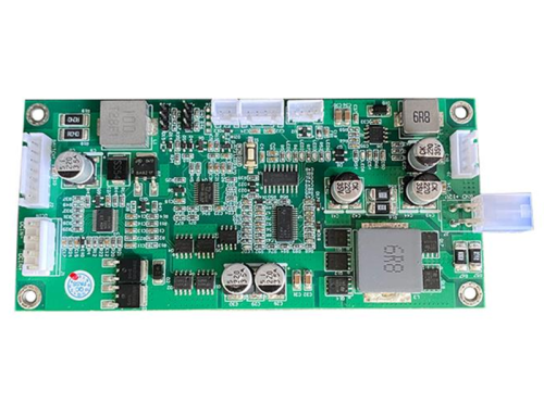
Connecting parallel cell groups with cross-over matrix nickel bridges balances voltage potentials across all 4S series nodes, enabling reliable Smart BMS cell monitoring. In a 4S4P 18650 pack without cross-connections, small variations in individual cell internal resistance ($\Delta R_{\text{DC}}$) cause voltage divergence between parallel branches during high-current discharge pulses. Cross-connecting the parallel nodes in a 4S matrix configuration allows balancing currents to flow laterally between parallel cells. This matrix topology maintains uniform node voltages across the 4S series string, enabling Texas Instruments BQ40z50 gas gauge ICs to read true node potentials without interference from localized trace voltage drops.
How to Select and Size Nickel Tabs for 4S4P 18650 Battery Pack Spot Welding?
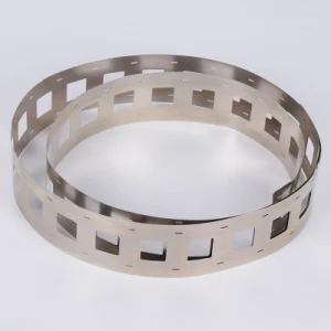
Selecting N6 pure nickel or copper-nickel composite strips with a current density below $10\text{ A/mm}^2$ prevents tab overheating and voltage drop during continuous 10A to 15A medical equipment discharge cycles.
Material Selection: N6 Pure Nickel vs. Copper-Nickel Composite Strips
Copper-nickel composite tabs provide three times the electrical conductivity of standard pure nickel, making them ideal for high-drain 4S4P medical battery packs. While nickel-plated steel is common in low-cost consumer electronics, its high electrical resistivity ($\approx 12.0 \times 10^{-8} \, \Omega\cdot\text{m}$) causes severe Joule heating at high discharge currents. N6 grade pure nickel ($>99.6\%$ Ni) offers excellent corrosion resistance and low resistivity ($\approx 6.84 \times 10^{-8} \, \Omega\cdot\text{m}$), making it the standard choice for medical 18650 packs. For high-power medical applications—such as motorized surgical tools or portable oxygen concentrators requiring continuous 15A output—copper-nickel composite strips (a copper core clad with pure nickel) reduce electrical resistivity to $\approx 2.20 \times 10^{-8} \, \Omega\cdot\text{m}$, reducing busbar $I^2R$ power losses by up to 65%.
Cross-Sectional Sizing and Current Density Thresholds for 4S4P Nickel Tabs
Maintaining nickel tab current density below $10\text{ A/mm}^2$ limits busbar temperature rise to under $5^\circ\text{C}$ during full-load 4S4P discharge. To size nickel tabs correctly, engineers must calculate the maximum continuous current passing through each segment of the 4S4P busbar. In a 4S4P pack discharging at 12A total continuous current, each of the 4P parallel cells supplies 3A. However, the main collector busbar connecting the 4S series nodes must carry the full 12A. The cross-sectional area ($A = \text{width} \times \text{thickness}$) must be selected to keep current density $J = I/A \le 10\text{ A/mm}^2$.
| Busbar Material Type |
Strip Thickness & Width |
Cross-Sectional Area (A) |
Max Continuous Current (J≤10 A/mm2) |
Expected Temp Rise (ΔT at 12A) |
| N6 Pure Nickel |
$0.15\text{ mm} \times 6.0\text{ mm}$ |
$0.90\text{ mm}^2$ |
$9.0\text{ A}$ |
$+12.5^\circ\text{C}$ (High) |
| N6 Pure Nickel |
$0.20\text{ mm} \times 8.0\text{ mm}$ |
$1.60\text{ mm}^2$ |
$16.0\text{ A}$ |
$+3.8^\circ\text{C}$ (Optimal) |
| N6 Pure Nickel |
$0.30\text{ mm} \times 10.0\text{ mm}$ |
$3.00\text{ mm}^2$ |
$30.0\text{ A}$ |
$+1.2^\circ\text{C}$ (Conservative) |
| Copper-Nickel Composite |
$0.15\text{ mm} \times 8.0\text{ mm}$ |
$1.20\text{ mm}^2$ |
$24.0\text{ A}$ |
$+1.8^\circ\text{C}$ (High Conductivity) |
What Welding and Structural Assembly Methods Ensure Low Resistance in 4S4P Packs?
Precision micro-joining using slitted nickel tabs and dual-pulse resistance spot welding eliminates cold welds and minimizes contact resistance across 18650 terminal caps.
Slitted Nickel Tab Geometry and Projection Welding Optimization
Center-slitted nickel tabs force welding current through the 18650 cell cap, creating consistent, low-resistance weld nuggets without damaging internal separators. Solid nickel tabs without slits allow a significant portion of the spot welding current to shunt through the nickel strip itself rather than passing through the 18650 nickel-plated steel top cap. Adding a $0.5\text{ mm}$ to $1.0\text{ mm}$ center slot (slit) between the two welding electrode tips forces current down into the cell terminal, creating two uniform weld nuggets with joint contact resistance below $0.5\text{ m}\Omega$. Dual-pulse inverter spot welders precisely regulate energy delivery (typically 25 to 40 Joules), preventing thermal burn-through of the top cap seal.
Thermal Dissipation and UL 94-V0 Holder Integration in 4S4P Packs
Integrating UL 94-V0 flame-retardant cell holders with silicone thermal pads maintains inter-cell spacing and routes busbar heat away from 18650 cell bodies. Placing 18650 cells in direct contact without structural holders accelerates thermal cross-talk between adjacent cells. Utilizing flame-retardant polycarbonate-ABS (PC-ABS) cell holders maintains a uniform $1.0\text{ mm}$ air gap between all 16 cells in the 4S4P matrix. Applying high-dielectric silicone thermal pads ($\ge 3.0\text{ W/m}\cdot\text{K}$) over the nickel busbars transfers Joule heat directly to the aluminum outer casing, keeping internal cell temperatures well within the $60^\circ\text{C}$ operating limit mandated by IEC 62133-2.
How Does Optimized Busbar Design Enhance Medical Compliance and BMS Performance?
Uniform busbar current distribution ensures accurate SMBus fuel gauge voltage measurements and prevents single-fault thermal runaway under IEC 62133-2 and IEC 60601-1 testing.
Reducing BMS Voltage Sensing Errors and Fuel Gauge Drift
Equalizing IR drop across 4S series connections enables BQ40z50 gas gauge ICs to report State-of-Charge (SOC) within $\pm 1\%$ accuracy. When a 4S4P battery pack operates under heavy discharge loads, high busbar resistance creates parasitic voltage drops ($\Delta V = I \cdot R_{\text{busbar}}$) along the PCB sensing traces. If the BMS voltage sense wires measure node potentials across resistive nickel tabs, the fuel gauge IC underestimates actual cell voltage during high-current pulses. Implementing low-resistance copper-nickel busbars and dedicated, low-current sensing traces eliminates load-induced measurement error, preventing premature under-voltage lockout (UVLO) tripping in critical patient monitors.
Preventing Single-Fault Thermal Overload in Sealed Medical Housings
Balanced current paths eliminate localized hot spots, preventing thermal runaway propagation during continuous duty in IP67-sealed medical instruments. Medical devices operating in sterile or field environments utilize unventilated, fluid-resistant enclosures. Under IEC 60601-1 single-fault testing (such as shorting a balancing resistor or operating at maximum ambient temperature), an imbalanced 4S4P pack with thin nickel tabs can experience busbar temperatures exceeding $100^\circ\text{C}$. Sizing nickel tabs for low current density ($J \le 10\text{ A/mm}^2$) and balancing current paths ensures the entire 16-cell pack maintains thermal equilibrium, satisfying medical single-fault safety mandates.
Developing a medical-grade 4S4P 18650 power system requires balancing electrochemical cell selection, busbar geometry, and low-resistance welding processes. For engineering teams evaluating overall pack architectures, comparing cylindrical cell dimensions is another critical step—read our technical analysis on 18650 vs 21700 for portable medical devices to determine the optimal form factor for your chassis footprint.
Request Custom 4S4P Engineering Support & STEP CAD Models
Partner with Tefoo Energy’s application engineering team to optimize your medical battery pack architecture. Submit your load profile and space constraints to receive custom busbar thermal simulations, 3D STEP CAD models, SMBus protocol specifications, and IEC 62133-2 certification support.
Frequently Asked Questions
Q1: What nickel tab thickness is recommended for a 12A continuous 4S4P 18650 pack?
A 0.20 mm thick by 8 mm wide N6 pure nickel strip or 0.15 mm copper-nickel composite tab is recommended.
-
Maintains current density below $10\text{ A/mm}^2$ across 4P collector nodes.
-
Limits busbar temperature rise to under $5^\circ\text{C}$ during full discharge.
-
Ensures low-resistance spot welding without damaging cell caps.
Q2: Why is diagonal load tapping essential in 4S4P 18650 battery packs?
Diagonal load tapping equalizes total electrical path resistance across all four parallel cells.
-
Prevents the first parallel cell from carrying excessive current load.
-
Eliminates localized thermal hot spots in parallel cell groups.
-
Ensures uniform cell aging across the entire 16-cell 4S4P matrix.
Q3: How do slitted nickel tabs improve spot weld quality in 4S4P battery assembly?
Slitted tabs force the welding current through the 18650 terminal cap rather than shunting through the nickel.
-
Creates two distinct, low-resistance weld nuggets ($\le 0.5\text{ m}\Omega$).
-
Reduces required welding energy, preventing thermal seal damage.
-
Improves mechanical shear strength under IEC 60601-1 vibration tests.
Q4: Can copper-nickel composite tabs replace pure nickel in medical 18650 packs?
Yes, copper-nickel composite tabs offer three times higher electrical conductivity than pure nickel.
-
Reduces busbar $I^2R$ resistive heating by up to 65%.
-
Allows thinner tab dimensions in space-constrained medical enclosures.
-
Features a weldable outer nickel layer for standard resistance welders.
Q5: How does busbar resistance affect Smart BMS fuel gauge accuracy in 4S4P packs?
High busbar resistance creates parasitic voltage drops that distort BMS voltage sense readings.
-
Causes fuel gauge ICs (like TI BQ40z50) to underestimate cell voltage under load.
-
Triggers premature under-voltage lockout (UVLO) in medical devices.
-
Low-resistance busbars maintain State-of-Charge (SOC) accuracy within $\pm 1\%$.